You are a brave wire bonder, so suggest to stagger the leads, one up, one down, put a "U" shaped curve to the pre-stripped W/W wire, so that it hangs on the IC lead, or you can squeeze on the IC lead to hold it in place, working with your tweezers and a pre-tinned iron. and your off to the races. I have done it before, it is a slow process.The flying IC/bug technique!! Almost can call it art when your done.I am sure your friends or wife/GF will be impressed with your dexterity and attention to detail ")
People especially older folk, are scared of SMDs, but I think it is actually easier and faster than PTH. SM Passives are really nice to work with assuming you have two irons avail.. Keep up your good work. If you help/support I am here for you.
Rick
People especially older folk, are scared of SMDs, but I think it is actually easier and faster than PTH. SM Passives are really nice to work with assuming you have two irons avail.. Keep up your good work. If you help/support I am here for you.
Rick
Wife not impressed good idea about alternating leads but they are so short to start with not sure how much they will move. There is no room to make a U to hang or anything, I have to carefully line up the wire and use the iron to heat the wire to act essentially like a miniature iron to heat and melt solder on lead and attach wire. It's not the prettiest job but I hope it works.
good idea about alternating leads but they are so short to start with not sure how much they will move. There is no room to make a U to hang or anything, I have to carefully line up the wire and use the iron to heat the wire to act essentially like a miniature iron to heat and melt solder on lead and attach wire. It's not the prettiest job but I hope it works.Good idea!
That's a good idea Rick.
Mark
..... so suggest to stagger the leads, one up, one down, Rick
That's a good idea Rick.
Mark
I guess wire loop is okay for SOIC @ 50 mil pitch, not so, it seems for 1mm (2x0.5mm pitch)
I just checked the DS (TPA3118D2,DAP (32-pin HTSSOP Pad-down)), the package is 0.65mm pitch, well that makes it so much easier
You can bend those leads all the way, opposite dir from each other, one time only however, after that leave them alone.
I remember we used to solder 30AWG onto QFP leads @ 0.5mm pitch. Needed to hook up to the logic analyzer. We used a Leica Stereo microscope to do the soldering, but that was HP and they could afford such luxuries, us DIYers have to make due.
Printed circuit boards on the cheap!
Hey X, and all interested,
I just read on another thread about a company that will make you printed circuit boards cheap!
It's called "3 PCB special"
Just read posts 1 through 4 here:
http://www.diyaudio.com/forums/solid-state/213020-new-home-brew-amp-module-3.html#post3392754
--Mark
Hey X, and all interested,
I just read on another thread about a company that will make you printed circuit boards cheap!
It's called "3 PCB special"
Just read posts 1 through 4 here:
http://www.diyaudio.com/forums/solid-state/213020-new-home-brew-amp-module-3.html#post3392754
--Mark
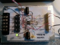
The ones pictured are Bournes 10 uH 6 amp, 0.497 x 0.497 in. Digikey. $0.92 ea. I also plan on trying thru hole ones at 3 amps, cheaper at $0.80 but smaller.
I am using circuit from TI's website for TPA31xxD2 actually the eval board circuit but slightly modified to go with fixed gain rather than with pot.
http://www.ti.com/litv/pdf/slou336a
I am using circuit from TI's website for TPA31xxD2 actually the eval board circuit but slightly modified to go with fixed gain rather than with pot.
http://www.ti.com/litv/pdf/slou336a
Last edited:
Hey X, and all interested,
I just read on another thread about a company that will make you printed circuit boards cheap!
It's called "3 PCB special"
Just read posts 1 through 4 here:
http://www.diyaudio.com/forums/solid-state/213020-new-home-brew-amp-module-3.html#post3392754
--Mark
This place will do 10 boards for $10, 2x2 in 2 layers. You can't beat that.
[PCB Prototyping] Green 2 Layer 5cm*5cm max -10pcs [PCB Prototyping] Green 2 Layer 5cm*5cm max -10pcs [PPB001] - $9.90 : iStore, Make Innovation Easier
I just have to install Eagle CAM software and learn how to use it to generate the Gerber files, looks like a whole 'nother rabbitt hole I am about to go down with this...
Last edited:
I guess wire loop is okay for SOIC @ 50 mil pitch, not so, it seems for 1mm (2x0.5mm pitch)
I just checked the DS (TPA3118D2,DAP (32-pin HTSSOP Pad-down)), the package is 0.65mm pitch, well that makes it so much easier
You can bend those leads all the way, opposite dir from each other, one time only however, after that leave them alone.
I remember we used to solder 30AWG onto QFP leads @ 0.5mm pitch. Needed to hook up to the logic analyzer. We used a Leica Stereo microscope to do the soldering, but that was HP and they could afford such luxuries, us DIYers have to make due.
I will try the staggering on the output pins to make clearance for thick 22 awg output wires thst go to the inductors. I get, bend is 1 time operation, they break if you bend them again.
I used to have a Leica stereo microscope at work too. Nice....
I am wondering how to jerryrig a hestsink for the powerpad now that it is up. A copper penny soldered edge on? I can cut some copper tubing and make a sheet approx size of recommended one. This thing needs to dissipate 10% of 25 watts or 2.5 watts at peak load.
You are assuming a steady state signal such as a sine wave. If you are going to do testing, using sine waves approaching clipping then yes a HS is needed. Music is not the same as a sine wave, the avg power is less.This thing needs to dissipate 10% of 25 watts or 2.5 watts at peak load.
You are right, that is worst case, for music, probably no heat sink needed. It has auto thermal shutdown too so no harm in pushing it. Some deep bass notes may cause it to trip if built in thermistor senses 150 C or above. I am kind of getting excited about making my own pcb now that folks on this forum have given me tips on Eagle and where to get them fabbed. I always thought doing my own smd pcb was out of my league but it is looking more and more like a possibility. I want to make this thing as small as possible for grins like maybe 1.5 x 2 in ? The inductors and power caps are the size limiters. If I go with flying leads I can save a lot of real estate and costs by not having screw terminals. The TPA3116D2 is a 50 watt per channel chip that is the same pinout and size. A 50 watt hifi amp the size of a large postage stamp is nuts.
Update on foam core amplifer
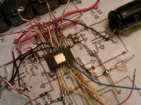
Life has been getting in the way of diy'ing lately and it has been very hard to find time to do precision work. Having to sit down with magnifying goggles, have undisturbed quiet time, and clear eyes and mind to manipulate a 0.6mm pitch lead with a fat soldering tip is tough. Nonetheless, I have made some progress and have about 6 leads to go on the 32 lead flip chip dead bug amp mounted on foam core board.
The 'large' bare copper wires are the main leads running from the amp to the inductors - these are 22 awg. Using that for Vcc and ground bus.
Attachments
Hi,
what is the difference between a TPA3123d2 board available on ebay for
$16, shipping included, and the TPA3118d2 you guys are challenging yourselves with?
2x50 w Stereo Class D Audio Power Amplifier Circuit Board TI TPA3123 | eBay
what is the difference between a TPA3123d2 board available on ebay for
$16, shipping included, and the TPA3118d2 you guys are challenging yourselves with?
2x50 w Stereo Class D Audio Power Amplifier Circuit Board TI TPA3123 | eBay
http://www.ti.com/lit/ds/symlink/tpa3123d2.pdf
http://www.ti.com/lit/ds/symlink/tpa3116d2.pdf
1. The modulation scheme is different for the ...16d2 part...read data sheet carefully
2. ...23d2 board at 50W out (@10% thd by the way) would dissipate close to 5W
I don't see much of a heat sink other than the board...hope they did it right.
3. We don't know what parts are used in that design...are the filter inductors able to handle 6A without saturation...are the power supply filter caps low esr types...what is the low end roll-off on the input caps...so many questions.
4. Where is the fun in just buying something you can make?
That is why it is called diy and not ibioeb (I Bought It On E-Bay)
I could make a reasonable enclosure for my ebay purchase, but I could not assemble a board, I made a horrible mess of replacing some components in a tube amp!
Would making a box qualify as diy as does pimping up a Lepai 2020a? ;-)
For the price of Chinese d-amp boards is it worth studying the specs? It is very hard to be disappointed.
Would making a box qualify as diy as does pimping up a Lepai 2020a? ;-)
For the price of Chinese d-amp boards is it worth studying the specs? It is very hard to be disappointed.
If your diy project is to put that amp in a box then that is what it is.
No-one should have a problem with that.
I can't build an integrated circuit. We all have to start with whatever building blocks we can deal with...or wish to attempt.
Sometime we fail. Sometimes we don't.
"It is better to have tried and failed than never to have failed at all."
That is DIY.
Be proud of (and share) what you can do.
Have fun
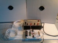
Introducing the Foam Core Amp - TPA3118D2
I finally had time to put the last "wire bonds" onto the upside down SMD flip chip. I put my 10x loupe on and carefully looked the connections over, and compared to schematic, then used a continuity tester and checked to see if "ground" shows up on any of the pins that it shouldn't. Ugg, one of the pins that should show +100k ohm on the gain setting section went to GND.
It turns out one of the 1 uF caps was bad and shorted (I probably fried it by applying too much heat during soldering). I swapped out the bad cap. Connected my foam core micro 14-inch Cornu spiral horn speakers, connected my old linear (transformer and 7812 based) bench power supply, connected to balanced inputs to an old headphone 3.5 mm jack and cable, plugged that into my source (a BB). Put on Led Zeppelin's "Stairway to Heaven" for the inaugural song. Crossed my fingers, pushed the power button on the supply. The LED lit, and good clean sounding Robert Plant's voice filled the room! I smiled and had a big ear-to-ear grin.
My first Class D amp, and I did it with a dead bug point-to-point wiring with all SMD components! The whole business with gluing the SMD parts to a piece of paper with the schematic drawn on it, and soldering point-to-point connections works! It sounds great. I did not take it too loud as I do not have any heat sinking or even solder connecting the powerpad to the groundplane for dissipation. It got pretty loud still.
If I had dedicated time, this would not have taken too long. But having to work in 1 hr increments took 8 hrs to do this. Being smarter and learning the tricks, I think I can go faster next time. Next time I will buy a 0.015 inch tip for my soldering iron and 0.015 in dia solder. Anyhow, here is the picture of the completed Foam Core Amp, and the Foam Core Audio System.
Did you guys have doubts that this would work?
Attachments
- Home
- Amplifiers
- Class D
- Cheap TPA3118D2 boards, modding them and everything that comes with it