Hi I'm currently working on a fully discrete class D amplifier for my undergraduate senior design project as a Computer Engineer.
I have no prior experience to anything that relates to this topic so I thought I would create this thread for continous discussion and opinions on choices I make throughout this process of building the amplifier. A lot of help would be greatly appreciated!
Okay, so far based on researched a Class D amplifier looks similar to this (http://upload.wikimedia.org/wikipedia/commons/thumb/4/4c/Pwm_amp.svg/800px-Pwm_amp.svg.png)
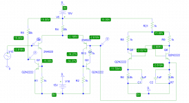
I was able to create a small differential amplifier to act as a comparator and a triangle waveform generator with all discrete components (See attachment.) So far my pspice looks promising and to be honest this is as far as i've gotten X_x. (WIP!). Any opinions or advice? I'll try to somewhat, log my progress and hopefully be able to have fully functional discrete class D further down in time. Thanks!
I have no prior experience to anything that relates to this topic so I thought I would create this thread for continous discussion and opinions on choices I make throughout this process of building the amplifier. A lot of help would be greatly appreciated!
Okay, so far based on researched a Class D amplifier looks similar to this (http://upload.wikimedia.org/wikipedia/commons/thumb/4/4c/Pwm_amp.svg/800px-Pwm_amp.svg.png)
I was able to create a small differential amplifier to act as a comparator and a triangle waveform generator with all discrete components (See attachment.) So far my pspice looks promising and to be honest this is as far as i've gotten X_x. (WIP!
). Any opinions or advice? I'll try to somewhat, log my progress and hopefully be able to have fully functional discrete class D further down in time. Thanks!Attachments
hi dakar in your project are you planning to go ucd or nonucd ?
you can check on sodvak he has many designs and class d 4 sure also try the below links you might learn a thing or two on fully discreet class d versions.
http://www.diyaudio.com/forums/class-d/85389-philips-ucd-application-note.html
http://www.diyaudio.com/forums/class-d/218564-my-first-ever-discrete-class-d-aud-amp.html
diysmps
http://www.diyaudio.com/forums/class-d/91773-pictures-circuits-my-diy-class-d-other-projects.html
http://www.diyaudio.com/forums/class-d/110165-my-diy-ucd-amp-junk-box.html
Class D.fromru.com
http://www.diyaudio.com/forums/clas...ly-differential-full-bridge-450w-rms-amp.html
http://www.diyaudio.com/forums/class-d/205654-ultra-simple-class-d.html
diysmps
Index of /Audio/Circuits/POWER AMPLIFIERS-CLASS-D
http://www.diyaudio.com/forums/class-d/55385-my-diy-ucd.html
visit the above links and have lots of fun
Last edited:
@sweetperfume
I actually tried to PSPICE the Philips UCD but my results were a little odd. (See attachment) It seems that my output was always the Vcc/Vdd of the circuit. It may be because of the parts I chose but those were the only ones available to me in the student edition? Or something in my setup is wrong?
Also, I don't understand the Philips one so well X_x I can't tell what part is the comparator or if there's a triangle wave generator I made a circuitlab.com of this as well found here. for reasons I don't know why since it compiles REALLY slow online
@stewin
I'm not sure whether to go UCD or nonUCD as I'm not entirely sure what that means... but I have been snooping for quite sometime and I've looked at some of those threads. Unfortunately some of them hosted schematics or posted links elsewhere that they're no longer available.
@Soldermizer
My professor actually allows vaccum tubes to be used in my project but they're quite outdated aren't they? Here's his specifications and his mention of vaccum tubes for reference (here)
Thanks everyone for the advice!
I actually tried to PSPICE the Philips UCD but my results were a little odd. (See attachment) It seems that my output was always the Vcc/Vdd of the circuit. It may be because of the parts I chose but those were the only ones available to me in the student edition? Or something in my setup is wrong?
Also, I don't understand the Philips one so well X_x I can't tell what part is the comparator or if there's a triangle wave generator
I made a circuitlab.com of this as well found here. for reasons I don't know why since it compiles REALLY slow online@stewin
I'm not sure whether to go UCD or nonUCD
as I'm not entirely sure what that means... but I have been snooping for quite sometime and I've looked at some of those threads. Unfortunately some of them hosted schematics or posted links elsewhere that they're no longer available.@Soldermizer
My professor actually allows vaccum tubes to be used in my project but they're quite outdated aren't they? Here's his specifications and his mention of vaccum tubes for reference (here)
Thanks everyone for the advice!
Attachments
@sweetperfume
I actually tried to PSPICE the Philips UCD but my results were a little odd. (See attachment) It seems that my output was always the Vcc/Vdd of the circuit. It may be because of the parts I chose but those were the only ones available to me in the student edition? Or something in my setup is wrong?
Also, I don't understand the Philips one so well X_x I can't tell what part is the comparator or if there's a triangle wave generator
@stewin
I'm not sure whether to go UCD or nonUCD
@Soldermizer
My professor actually allows vaccum tubes to be used in my project but they're quite outdated aren't they? Here's his specifications and his mention of vaccum tubes for reference (here)
Thanks everyone for the advice!
I too got same prob with philips amp but no worries buddy.. Its the problem that your negative switches are unable to get the bias 12v supply....just check it out and dont use powerful transistors...use high voltage low power transistors only.....and set the freq and dead time properly...
I actually tried to PSPICE the Philips UCD but my results were a little odd. (See attachment) It seems that my output was always the Vcc/Vdd of the circuit. It may be because of the parts I chose but those were the only ones available to me in the student edition? Or something in my setup is wrong?
I guess it will start up, when you define the initial condition of C8.
Put its innitial condition to 12V (or -12V, this depends on your chosen orientation during placement of C8).
I actually tried to PSPICE the Philips UCD but my results were a little odd. (See attachment)
Hi
Looking at your schematic, the first thing I notice is that the bottom left corner should not be connected to ground, but to ground via a cap, like you do in the upper left corner.
@stinius
Thanks I just noticed that as well but it didn't seem to make a difference in my simulation X_x
@sweetperfume
I'm not sure but on PSPICE my output is always 35V as shown in my attachments in post 5 X_x. It's also hard to understand parts of the design as to what they do :/
Thanks I just noticed that as well but it didn't seem to make a difference in my simulation X_x
@sweetperfume
I'm not sure
but on PSPICE my output is always 35V as shown in my attachments in post 5 X_x. It's also hard to understand parts of the design as to what they do :/Take a bread board and start with philips ucd and dont attach fets untill you think that every thing is clear use 24volts supply for start up...and use slow fet like 250n....on philips said you can see R9 330 ohms resistor....place a differential resistor instead....you get all fine
@stewin
I'm not sure whether to go UCD or nonUCD
Thanks everyone for the advice!
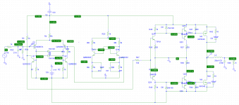
in your schematic please replace all diodes with high speed ones e.g 1n4148 and d4 and d12 make sure you use mur120 or uf4007 to be on the safe side.
q11 use tip41 or bd139 .
http://www.diyaudio.com/forums/atta...ly-discrete-class-d-amplifier-wip-capture.jpg
Last edited:
Just finished swapping out those diodes with the ones you requested. I still feel like I set something up wrong since my output is always a constant 35V or is that how it is on transient solver?
anyways hopefully tonight I can mess with it more and figure out what I can do. Thanks
anyways hopefully tonight I can mess with it more and figure out what I can do. ThanksAttachments
Alright, so I've been working on my amplifier again and also a replicate of the Phillips UCD.
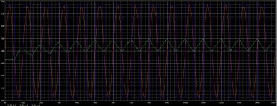
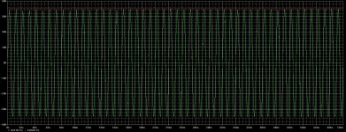
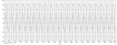
I think I figured out why my output is always just my power supply voltage. I've been taking the voltage reading AFTER the inductor as opposed to before it. (Attached is the results of taking the readings of input v. output before inductor. The Philips UCD schematic is attached a page back.)
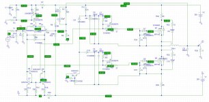
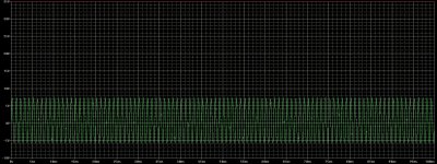
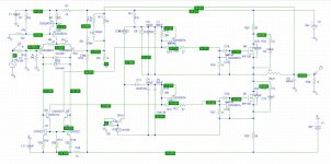
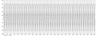
I also have my own class D design going as well which is attached below (2nd picture. Results 3rd picture) Let me know what you guys think! The driver portion of the design was taken from diyaudio's very own stewin. Thank you very much and I hope it's okay X_x.
I still have to figure out how to tweak it so that it's in line with my professor's specifications but I think this is a start for me.
I think I figured out why my output is always just my power supply voltage. I've been taking the voltage reading AFTER the inductor as opposed to before it. (Attached is the results of taking the readings of input v. output before inductor. The Philips UCD schematic is attached a page back.)
I also have my own class D design going as well which is attached below (2nd picture. Results 3rd picture) Let me know what you guys think! The driver portion of the design was taken from diyaudio's very own stewin. Thank you very much and I hope it's okay X_x.
I still have to figure out how to tweak it so that it's in line with my professor's specifications but I think this is a start for me
.Attachments
Hi Guys,
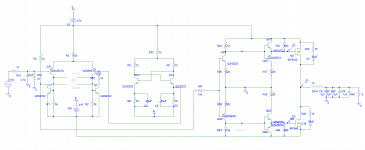
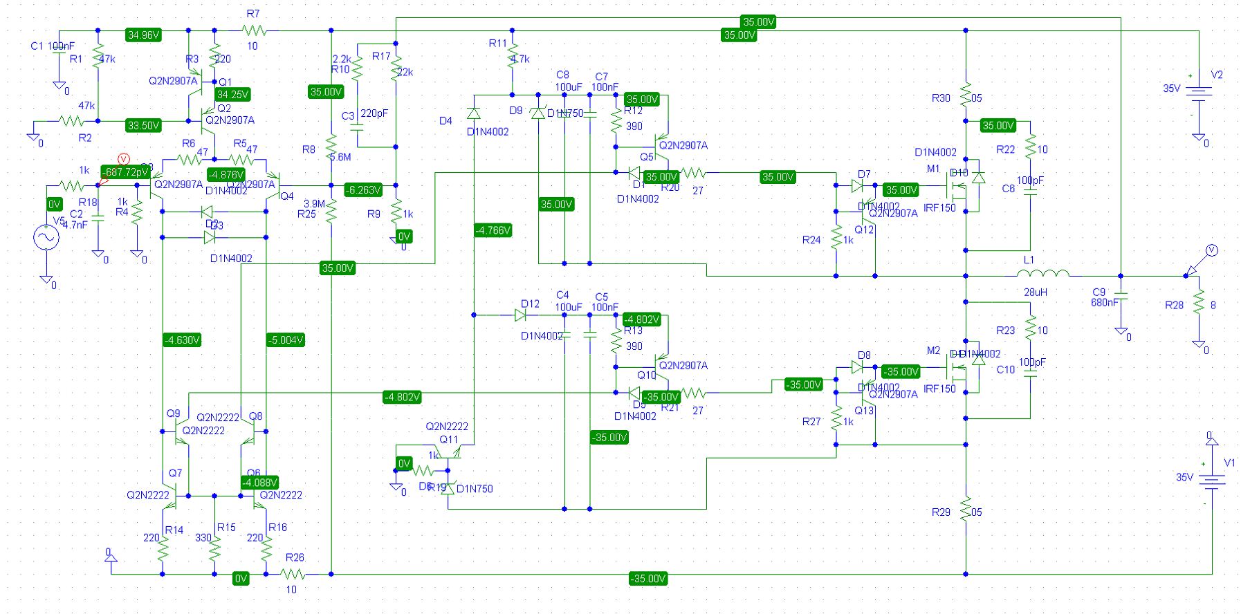
So I finally bread boarded this circuit (attached below is the updated schematic).
I've tested having an input from a Function Generator and the output to a speaker. Tested some freq from 20Hz to 10kHz which you can hear the pitch sound.
My problem now is figuring out how to get an audio signal in (perhaps my cellphone's headphone jack?) as the input.
I bought a 3.5mm jack (CA-2205 Tensility International Corp | CP-2205-ND | DigiKey) and I've tried plugging my cellphone in, (Red wire as input, blacks to ground. I believe the smaller black is for another channel..)
The problem is I'm not getting any sound. I'm guessing my cellphone does not output voltage ? X_x I'm not entirely sure how to work with the 3.5mm as I've never worked with one before. Any help would be appreciated!
Attachments
Can try something like this. Not *exactly* discrete, but I think of comparators as time-savers rather than ICs.
http://t3sl4.dnsdynamic.net/Current Mode Buck.pdf
Tim
http://t3sl4.dnsdynamic.net/Current Mode Buck.pdf
Tim
Can try something like this. Not *exactly* discrete, but I think of comparators as time-savers rather than ICs.
http://t3sl4.dnsdynamic.net/Current Mode Buck.pdf
Tim
for such low wattage the schematic is complecated maybe the link can be considered an option http://www.diyaudio.com/forums/class-d/205654-ultra-simple-class-d-26.html#post3213886
That's one hell of an ask for an undergraduate project - certainly far more ambitious than anything I was ever asked to contemplate at university.
A response to 100kHz seems barely feasible - surely that'd take your switching speed close to 1MHz or even beyond. Good luck & keep us posted!
On the subject of valves (or tubes), I'm sure I remember reading about PWM choppers built from valves being used as VCAs before the advent of transistors.
A response to 100kHz seems barely feasible - surely that'd take your switching speed close to 1MHz or even beyond. Good luck & keep us posted!
On the subject of valves (or tubes), I'm sure I remember reading about PWM choppers built from valves being used as VCAs before the advent of transistors.
- Status
- This old topic is closed. If you want to reopen this topic, contact a moderator using the "Report Post" button.
- Home
- Amplifiers
- Class D
- Fully Discrete Class D Amplifier (WIP)