I was looking for the considerations while choosing / designing filter coil for ClassD amp, but couldn’t find satisfactory answer.For deciding the wire gauge of the coil what frequency for calculating skin effect needs to be taken into account? I.e. PWM frequency or 20 KHz.
Every current that flows with significant intensity must be considered.
Not only skin effect, proximity effect is much stronger! Skin effect is actually negligible.
The wire requirements depends heavily on the choke/core construction! Determining wire gauge regardless the choke/core shape is a bad idea.
The simple answer you expect does not exist.
Not only skin effect, proximity effect is much stronger! Skin effect is actually negligible.
The wire requirements depends heavily on the choke/core construction! Determining wire gauge regardless the choke/core shape is a bad idea.
The simple answer you expect does not exist.
Skin effect and proximity effect will both be small, although not negligible, at 20kHz where you want audio current to pass with low losses. Two other relevant frequencies are the switching frequency and the inverse of the rise time. Here your interest is to stop these getting through but not heat the coil too much. Having a slightly lossy coil at those frequencies might even help it work better by reducing circulating currents.
Why not copy an existing filter design?
Why not copy an existing filter design?
Skin effect loss is typically less than 0.05 % of nominal power with solid wire. So forget it!
Proximity effect loss can be as high as 1..2 % of nominal power, if geometry is not designed correctly!
Ways to improve:
1: reduce stray flux!
2: keep away wire from the (remaining) stray flux!
3: if the aboves can't be done, than use litze, or at least simple stranded wire!
Bad ideas:
No.1. Multilayer solenoid + air-core + solid wire.
No.2. Ferrite core with a big single gap + solid wire over the gap.
Good ideas:
...there are many!
Just curious...
Are you looking for a common mode or differential filter?
Pafi is right on the construction technique, the thing to remember is that the wires lying close to each other are in effect capacitors so a badly wound core can actually be worse that no inductor at all because the leakage and inner winding capacitances set up additional resonance points.
High perm cores are nice but in general, they lose their effectiveness above 1MHz. Above 1MHz you are generally relying on the inductor parasitics. Multi-layer construction using lower perm cores for lower frequencies is possible using multiple layers but care must be taken in sector winding the core and/or using insulating tape to carefully insulate the windings is helpful.
In general, rod/drum cores are the poorest filter types because they radiate badly, toroids are best in general but a standard ferrite saturates quickly if used as a differential inductor. Powdered iron (higher frequency) or amorphous cores are better (lower frequencies) for differential inductors because of the distributed air gap.
Attached is a commode mode choke example.
Tony
Attachments
See: http://www.ferroxcube.com/appl/info/gaptoroids.pdf
One vendors idea on what to do.
Ice Components ICE Components - Class D Inductors Pre-made for Class D
One vendors idea on what to do.
Ice Components ICE Components - Class D Inductors Pre-made for Class D
Thank you all for your contribution here.
I had googled a lot on design on filter inductor for ClassD amp. But did not find papers good enough that would let you design your own inductor. So I decided to initiate this thread. And probably complete solution can be found in this thread. So requesting all you magnetic gurus help this thread.
While doing this I was not sure how to do this. If I put the whole thing at a time then every member here would discuss different topics letting to scattered discussion and no topic would be discussed well.
Right now questions hitting my brain are as follows.( pls add yours too.)
1) If the classD amp PWM frequency is 450Khz, and the amp required bandwidth is 20Hz to 20Khz. Then what frequency should be considered , the PWM , 20Khz, or 20Hz. And why?
2) The same point above would also affect the energy storage calculation of the core.
3) This coil differs from our regular DC PWM power supply this also has swing of opposite polarity voltage at the input. So how would calculations differ from regular SMPS filter inductors?
4) Consideration of EMI , Proximity effect, were covered by Pafi & Tony.
@ stoc005 , thanks the link to Ferroxcube its good.
If you have any other point I am missing (may be my illiteracy) please be nice to put here.
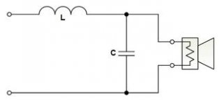
I am attaching the typical second order filter picture.
I had googled a lot on design on filter inductor for ClassD amp. But did not find papers good enough that would let you design your own inductor. So I decided to initiate this thread. And probably complete solution can be found in this thread. So requesting all you magnetic gurus help this thread.
While doing this I was not sure how to do this. If I put the whole thing at a time then every member here would discuss different topics letting to scattered discussion and no topic would be discussed well.
Right now questions hitting my brain are as follows.( pls add yours too.)
1) If the classD amp PWM frequency is 450Khz, and the amp required bandwidth is 20Hz to 20Khz. Then what frequency should be considered , the PWM , 20Khz, or 20Hz. And why?
2) The same point above would also affect the energy storage calculation of the core.
3) This coil differs from our regular DC PWM power supply this also has swing of opposite polarity voltage at the input. So how would calculations differ from regular SMPS filter inductors?
4) Consideration of EMI , Proximity effect, were covered by Pafi & Tony.
@ stoc005 , thanks the link to Ferroxcube its good.
If you have any other point I am missing (may be my illiteracy) please be nice to put here.
I am attaching the typical second order filter picture.
Attachments
(Simplified) designing order:
0. Requirements (Rl, P, etc...)
1. Power topology, modulation method
2. Feedback topology
2.a. zobel network design if needed
3. Inductance (+ capacitance) calculation
4. Core topology + material
5. Dimensions
5.a. if the proper size (or bigger) is not available, then go back to 3!
6. Number of turns, wire gauge
7. Loss estimation
8. if wire doesn't fit into the window, or loss is too high, then go back to 3. or 4.!
Every steps are based on the previous ones!
Every steps deserves a whole topic.
And if somebody wants to understand, then he must learn the basics of magnetics.
Last edited:
This should be an interesting thread!
Just for my curiosity, why is using a multi-layered air-cored inductor a bad idea? I read somewhere that an air-cored inductor was a better choice than one using a ferrite core for this application.
TIA,
Andy
Bad ideas:
No.1. Multilayer solenoid + air-core + solid wire.
Just for my curiosity, why is using a multi-layered air-cored inductor a bad idea? I read somewhere that an air-cored inductor was a better choice than one using a ferrite core for this application.
TIA,
Andy
Just for my curiosity, why is using a multi-layered air-cored inductor a bad idea?
Because the flux change penetrates into the wire, and induces very strong eddy currents, unless the wire is a fine litz wire. And more layers -> more flux density.
By the way, skin effect is a special kind of eddy current - generated by the own current of the wire.
I read somewhere that an air-cored inductor was a better choice than one using a ferrite core for this application.
Fortunately ClassD designers don't think this.
This should be an interesting thread!
Just for my curiosity, why is using a multi-layered air-cored inductor a bad idea? I read somewhere that an air-cored inductor was a better choice than one using a ferrite core for this application.
TIA,
Andy
Here's my US$0.02 on the multi layer issue. It fundamentally all comes down to inner winding capacitance layer to layer. You get an AC coupled path from th input to the output that allows the noise to bypass the inductor. Think of it as a cap across the L.
The inner winding capacitance is always there but it can be mitigated but increasing the distance between the windings (i.e. tape between layers, thicker enamel and in the case of a toroid sector winding to minimize the voltage drop between the layers.
I like air-core inductors in one respect... they won't saturate (choice vs. ferrite). The down side is that for a decent inductance you need a lot of turns and you have a really big antenna area.
Tony
Here is your differential loaded inductace low pass filter and a sample of a 60Hz Phase differential inductor I did for an AC line heater application. The principle is the same for Audio as it is for power applications.
Design your low pass filter, set our load lines and then figure out what your inducatnce will look like over your load range. Another nice thing about aircore inductors us their impedance doesn't change much. A decent alternative to the aircore is the Micrometals -10 material. Pretty much a flat impedance out a really long ways. I've used them in resonant applications to great effect.
Tony
Attachments
Apologies you all for not being here. My project code got corrupted and had to write all again. Luckily I had partially archived it safe.
Once again thanking you for the words of knowledge.
@ pafi
We would soon put my understanding on the points you have mentioned. pl. give me some time.
@ dtproff,
I just downloaded the the sheets and trying to understand them. I am trying to understand the sheet "Mathcad - 60Hz Inductor.pdf" in depth. Soon would come with some queries
Tony, your tuts on transformer design is helping me a lot...")
Once again thanking you for the words of knowledge.
@ pafi
We would soon put my understanding on the points you have mentioned. pl. give me some time.
@ dtproff,
I just downloaded the the sheets and trying to understand them. I am trying to understand the sheet "Mathcad - 60Hz Inductor.pdf" in depth. Soon would come with some queries
Tony, your tuts on transformer design is helping me a lot...
Last edited:
Hello,
@ Tonny,
Its hard to find the T- core with u 10 ( Micrometals -10 material). and its difficult to cut any other T-core for the desired airgap. so for the moment seeing alternative as a EE core.
I am attaching the mathcad sheet its based on our discussion on your tuts. on ferrite transformer design. Pl go through and let me know any further changes need to be made
or the me and other readers can use this for their need?
( With intentions that same can be used with RM core to reduce EMI.)
Attachments
A writeup from Class-D Amplifiers
The ideal inductor (in terms of linearity) is an air-core one, but the size and number of turns required for typical Class-D operation usually makes it impractical, so a core is normally used in order to reduce turns count and also provide a confined magnetic field that reduces radiated EMI. Powder cores or equivalent materials are the common choice. It can also be done with ferrite cores, but they must have a "gap" where energy is stored. Wire size must also be carefully chosen so DC losses are low (requiring thick wire) but also skin effect is reduced (AC resistance must also be low).
Inductor core shape can be a drum core, gapped ferrite RM core, or toroidal powder core, among others. Drum cores have the problem that their magnetic field is not enclosed, hence producing more radiated EMI. RM cores solve this problem but have most of the coil enclosed, so cooling problems may arise as no airflow is possible. IMHO, toroids are preferred because they feature both closed magnetic field that helps control radiated EMI, a physically open structure that allows proper cooling, and easy and economical winding, as they don't need bobbins.
Last edited:
Hello, I used EE core for my classD. Working great. I used a single strand if 18 gauge Its at room temperature, Although I was expecting it to heat as per calculations. I have wrapped the joint of the core with copper foil [ hopping to reduce EMI because of fringing flux]. and Now this amp sounds very clean, no hiss too....
in the attached sheet, Bmax is close to 0.32T which makes me done with the winding in a single layer. So, I don't need to worry about the interlayer capacitance.
Next I am going to replace this coil with T-core. trying to find micrometal 10 material.
pl. let me know if I did any thing wrong in above.
Last edited:
Hello,
@ Tonny,
Its hard to find the T- core with u 10 ( Micrometals -10 material). and its difficult to cut any other T-core for the desired airgap. so for the moment seeing alternative as a EE core.
I am attaching the mathcad sheet its based on our discussion on your tuts. on ferrite transformer design. Pl go through and let me know any further changes need to be made
or the me and other readers can use this for their need?
( With intentions that same can be used with RM core to reduce EMI.)
The calculations look OK. I would rerun the them at 10Hz to see how things are working there to make sure I don't have a saturation issue. You stayed below my rule of thumb gap of 1mm.
Be careful with slow moving signals on this. A DC bias will saturate the core.
I suggest putting a resistive load on it and sweeping the output from 1Hz to 100KHz and measure the output. Look closely at the self resonance points of the filter itself. Also watch the feedback loop (if you are using one) to catch any signs of instability. You should see a fairly flat amplitude up to the corner frequency.
Tony
- Status
- This old topic is closed. If you want to reopen this topic, contact a moderator using the "Report Post" button.
- Home
- Amplifiers
- Class D
- considerations while choosing / designing filter coil for ClassD