Looks like 95 views and no responses. I kinda wonder about this myself, so I'll start this off. I googled:
PCM to PWM conversion - Google Search
The first hit is an older diyaudio thread.
Just thinking offhand, it might work better to convert not to PWM, but rather to a single-bit high-bit-rate (in the MHz range) "PCM", as used in the first stage of many sigma-delta converters. This makes the output quantized (the output always switches on a clock transition) just like DSD, but this might have a substantially higher switching frequency than Class D generally uses, causing some problems with output device switching speeds.
The volume would be controlled while in PCM (because I don't think it's readily doable as a 1 bit signal) - just multiply by a constant. With a 24-bit volume control word and a 24-bit PCM signal, the result is 48 bits which can probably be chopped (do bit reduction) back down to the 24 most significant bits without (much) audible damage, though it would be easy enough to add low-level dithering noise before the chop. If the source is 16 bits, make that 16 bits the most significant bits in a 24 bit word, then proceed as described.
Thesedays the faster 32-bit processors or microcontrollers (such as the latest ARM chips) should be fast enough to do the needed DSP work at 24/96 or so, though dedicated DSP chips are cheap enough as well.
I've done this professionally for a high power broadcast application. Things you need to know...
Doing digital generation of traditional PWM (comparing a triangle wave to your input signal) while maintaining 'audiophile' quality requires a brutally high PWM sampling rate. Technically Fs * 2^16 or >2GHz for 44.1KHz audio.
Doing noise shaping, you can gain a few bits back in the audio frequency band and bring the PWM generation frequency down to a 'practical' level - eg, 500MHz using the DDR outputs of a FPGA running at 250MHz. You can also add more PWM output channels and sum their outputs together, gaining an extra bit every time you double the number of PWM outputs.
You're better off ditching classical PWM and making a delta sigma modulator, with some tricks added like dynamic hysteresis to keep the switching frequency in a good place.
But in the end, digitally generated PWM will be limited in performance by power supply rejection/pumping, thermal effects due to output stage Rds(on), etc... effects which will likely overwhelm time quantization noise. You need to either sample your power supply voltage at a high rate with low delay to do feed forward compensation, sample the power stage output and do NFB, again with a brutally low delay... or characterize the response of your system, build a model for everything and do precorrection.
Best chip to develop such a thing would be a FPGA. Something like a Xilinx Spartan3-200A, which can run at a couple hundred MHz and has plenty of available multiplier blocks inside.
The internals of DAC and PWM is somewhat beyond me at the moment. The following video, however was an eye opener. Without watching the entire video, let me post parts of the transcript for some real game-changing stuff. ... Open Transcript. He also says we prefer distortion but don't know it.
The entire premise that we can only tell by listening, and that measurements are not enough is a real eye opener. If true, then I already have the equipment needed to analyse all audio systems for quality. Structured listening...
01:11
the interesting thing about high end
01:13
audio is that we have no understanding
01:17
how the brain processes audio
01:20
information simple thing how we separate
01:24
sounds out no understanding how about
01:27
how the brain does that functioning
01:30
psychoacoustic thresholds which are the
01:32
normal things that people work towards
01:34
....
extremely low now I know it's going to
05:50
be audible because I've dealt with this
05:52
kind of situation before but if you
05:53
spoke to a normal engineer and said this
05:57
level you're gonna hear he would say
05:59
that was impossible to hear so he can't
in terms of designing products has no
01:38
bearing on the brain processing it's all
01:41
about simple very simple things in
01:43
threshold of hearing so you can't make
01:46
any assumptions as to whether something
01:49
is audible not and the only way you can
01:51
do in terms of understanding whether
01:53
something is audible is to do a very
01:55
careful structured listening test audio
If you go to patents.google.com, enter PCM to PWM, it comes up with just a ton of material. Assignees being places like STM, Infineon, Pioneer, Sharp, TI, Intersil, Wolfson, etc.Hi,
I would like to learn more about PCM to PWM conversion. The theory and implementation basics. Old fundamentals, New developments/improvments/ideas. Any good links or books I can check out ?
Thanks.
US 7.626,519 B2 is such a patent assigned to TI; "Digital audio circuitry including modulation circuitry for generating a pulse-width modulated (PWM) signal from processed pulse-code modulated (PCM) audio signals. The modulation circuitry includes a duration quantizer function that generates a sequence of duration values d(k) from received PCM samples, quantized to integer multiples of periods of a master PWM clock."
Out of 14,500 results for such an inquiry, just the 1st two pages show there's more than one way to skin that cat. Google also provides a graph (on the upper right of the page) showing when the patents were issued, so you can get an idea of what's old and new - at least among issued patents on the subject.
Personally, I'd like to know if the amplifiers I'm listening to, the TAS5825, do that conversion entirely in the digital domain. I suspect yes, but know of no-one who could tell me definitively. Look up Lars Risbo, give him a call and ask... "Hvem var den skat?" ... "Nogle Nød"
Doing digital generation of traditional PWM (comparing a triangle wave to your input signal) while maintaining 'audiophile' quality requires a brutally high PWM sampling rate. Technically Fs * 2^16 or >2GHz for 44.1KHz audio.
Agree.
Let us first assume that the PWM fullscale voltage is same as the PCM fullscale voltage, say 1V. Now, for a one to one correspondence between the two methods, one step (delta = Fullscale/2^N) change in the PCM domain needs to map to exactly one step of pulsewidth.
PWM step width => PCM step voltage
=> 1V x Tstep / Tpwm = 1V / 2^N.
Thus, if the least useful pulsewidth is 10ns (reasonable value for today), then a clock frequency of 2/10ns = 200MHz is required to generate the PWM.
You may also calculate the PWM switching frequency period for 16 bits as 1/ (10ns x 65536) = 1.525kHz, which is barely sufficient for a 50Hz inverter.
With a 250kHz switching frequency, you may encode audio into the PWM. However, the clock frequency then would be:
2 x 250kHz x 65536 = 32.768GHz.
So, you get the idea why PDM (sigma-delta modulation) is recommended.
Last edited:
Nowadays there are highly affordable MCUs which generate PWM at extremely high resolutions, better than 500pS. They're not using clocks >2GHz though, they must be using on-chip analog delay circuits.
Here are a couple of examples : Infineon XMC4400 (150pS resolution) ST STM32G474 (184pS resolution)
Here are a couple of examples : Infineon XMC4400 (150pS resolution) ST STM32G474 (184pS resolution)
An old trick that works well is embedding a coarse pulse-width modulator in a sigma-delta loop, however, as gmarsh already wrote... The real problem is the conversion to analogue in the class-D stage. The supply is basically the DAC reference, so any signal-related ripple on the supply causes distortion and conversion of out-of-band quantization noise into the audio band. The usual solution is some kind of negative feedback from the class-D stage output, for example using an analogue pulse width modulator.
Nowadays there are highly affordable MCUs which generate PWM at extremely high resolutions, better than 500pS...
The MCUs can definitely make narrower pulses, but actual question is whether the MOSFETs in the power stage can do the same, which is the basis for the taking the bare minimum pulsewidth as 10ns. In most cases, even the dead-time is longer than this.
Yes, I meant to say that most MOSFETs cannot distinguish pulses narrower than 10ns. I didn't say jitter, as that's mostly used in communications. Since, the edge of the pulse is not rectangular due to the related resonances, the term "digital" loses its meaning, making things analogue altogether, also necessitating a feedback loop for error correction, as mentioned by MarcelvdG above.
newvirus2008 said:MOSFETs cannot distinguish pulses narrower than 10ns.
Please read the above as "pulsewidth changes narrower than"... Thanks.
Yes, but unfortunately it doesn't happen that way in actual practice, as the average pulse-width error (in ns) is itself often larger than 0.01ns. It's not "time quantisation" as such, but what happens is the fine pulse-width changes get buried in errors associated with the gate-drive and output stage (turn on/off delays, rise/fall times, dead-time etc.). You could call it "uncertainty" (like abraxalito said) if you want.
Ideally, the power stage responds to even the smallest changes in pulse-width to cause proportional changes in voltage, current, mmf, H-field and B-field of the output inductor to filter the audio. However, in actual practice, all these phenomena (including magnetic ones) have errors that limit the available resolution of an open-loop Class-D amplifier. Further, some of these errors also vary with environmental conditions such as temperature etc., making things even more complicated.
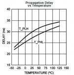
Please see the following screenshot from the datasheet for LM5113 (gate-driver) that has a 1.5ns delay matching, with operation beyond 2MHz (have used it myself). Even my figure of 10ns doesn't really stand !
Ideally, the power stage responds to even the smallest changes in pulse-width to cause proportional changes in voltage, current, mmf, H-field and B-field of the output inductor to filter the audio. However, in actual practice, all these phenomena (including magnetic ones) have errors that limit the available resolution of an open-loop Class-D amplifier. Further, some of these errors also vary with environmental conditions such as temperature etc., making things even more complicated.
Please see the following screenshot from the datasheet for LM5113 (gate-driver) that has a 1.5ns delay matching, with operation beyond 2MHz (have used it myself). Even my figure of 10ns doesn't really stand !
Attachments
A constant delay is only a steady-state error (like offset), but the power-stage errors are dynamic ones. In the PWM world, any timing error leads to a output voltage error, since voltages are represented by pulsewidths. Due to the nature of its internal operation, an inverter is inherently non-linear and needs to be linearised using negative feedback in order to be capable of competing with the dynamic range of digital systems.
Right from the time when the gate is driven, Vds falls (Vgs rises), giving the non-linear Miller effect that depends on MOSFET gain (dVds/dVgs). This renders most components of pulse-width error like rise time, fall time, delay times, Miller plateau voltage etc. to become both load current and temperature dependent. Dead-time error is also non-linear in its own right. And without post-filter feedback, the choke could also contribute its fair share of non-linearity due to its BH curve. Note that this is without considering Rds variation and power supply ripple.
It is thus almost impossible for small pulse-width changes to make their way to the speaker output, and they mostly end up swamped due to the aggregate error from all of the above.
Last edited:
Is there in theory an advantage doing a "short cut" PCM->PWM conversion without a pure analog intermediate step?
PCM->PWM I would argue still entails a D/A conversion as we go from an integer >1 to a (representation) of a discrete level. But this usually causes a wild debate som maye we should not venture into this...
Is there a real gain anywhere and what does it constitute?
Detailed process diagram comparison?
Math?
//
- Home
- Amplifiers
- Class D
- PCM to PWM conversion 101