Hi All,
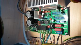
I recently bought this board and I see 50k trim pots. Does anyone know what these are for?
Thanks.
99% sure they must be to set output offset voltage (DC)
like in the case of all ta2020 muse, topping etc.
In case of the topping tp20 I measured 170 mV on one output channel and -26 mV offset on the other. I managed to adjust this to +/-1mV with the amp ON while connected to speakers (using a simple dc voltmeter connected to the output). After this I don't hear any dc click from the speakers when powering up. I also have a muse m20: the offset was already < 20 mV but still I adjusted to +/- 1 mV.
Hello
I bought LJM TA2022 class T Power amplifier board kit.
i am having a problem maybe someone can help? When the amp turns on the relay does not click and no sound is heard, If the relay is jumped the amp is working.
B: yes. 'm sorry I didn't see your question and answer time later.
Maybe you should be using the multimeter, measure OUT GND dc voltage.
Adjust the adjustable resistance make them close to 0 mv. Won't appear such relay protection
similar problem
Hi ljm,
I have a similar problem with TA2022 ver 1.2 board: I hear the relay click after 4 seconds but no sound at all. Also no noise from the speaker whatsoever.
I also tried a very cheap yuanjing board: this does amplify but noisy if unshielded.
I think the I am dong something wrong with the ver 1.2 board: the bridge jumper is not installed and I want to use stereo.
Please advise.
Greetings from the Netherlands
B: yes. 'm sorry I didn't see your question and answer time later.
Maybe you should be using the multimeter, measure OUT GND dc voltage.
Adjust the adjustable resistance make them close to 0 mv. Won't appear such relay protection
Hi ljm,
I have a similar problem with TA2022 ver 1.2 board: I hear the relay click after 4 seconds but no sound at all. Also no noise from the speaker whatsoever.
I also tried a very cheap yuanjing board: this does amplify but noisy if unshielded.
I think the I am dong something wrong with the ver 1.2 board: the bridge jumper is not installed and I want to use stereo.
Please advise.
Greetings from the Netherlands
Attachments
found an error; now the ver 1.2 is up and runnng: fantastic
hi all, and especially ljm:
I found that resistor 200R, just behind the 7805+cooler was loosened. By the way in schematics this resistor is depicted as diode????
Now the ver 1.2 runs perfectly and even in a open wooden testcase the noise is very low.
Compared to my topping tp20 the extra power is clear, nice bass!
I think I have a new favourite.
Happy holidays
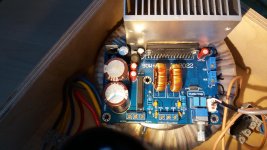
140vDC on + speaker terminal!
Hi LJM
I've got two of your green TA2022 boards. Both have worked fine for years but I recently mounted one to a new heat-sink and transformer. When I powered it back on, I hear the relay click after 2 seconds, but I'm measuring about 140v D/C on the speaker output! (No speaker connected)
The transformer is 44VCT. The amplifier is connected in bridge mode
I don't see any damage or shorts to the board or IC.
Any ideas?
Thanks
7805 current = 35MA
Its voltage = VCC-10V-5V
10V is the concatenation of the voltage divider resistors above.
7805 power consumption is about 15 * 0.035 = 0.52W. It is quite hot, but not dangerous.
Short out the input signal IN INGND. If there is no noise, it means the noise is caused by the input signal. Such things are more common.
Pay attention to the generation of the input signal interference. And ground handling.
Hi ljm, i'm trrying to repair an ta 2022 ver 1.1 is posible to have a schematic focused, i found one but the image is not focused
thank you .
my mail is l.pedrali@libero.it
Tried a different pre-amp and the buzz has gone.Still left with some hiss but it's very low level and doesn't intrude.
As I gave up trying to remove the 4700uF caps from the board I've wired the 6800 ones in parallel which hopefully will reduce 'bus pumping' effects.
There's still a heat issue of course but the amp seems quite stable and unaffected.
Bearing in mind the cost of the board I'm generally satisfied with it and the sound quality is excellent to my ears.
Do not try to replace the capacitor.
Because capacitance itself doesn't make a difference.
We can make an assumption. If 4700uf is replaced by 6800uf. 10% performance improvement
So it's hard for us to do an experiment, using 500000 UF directly. I actually did.
500000 UF capacitors are used. There was almost no change in all the circuits.
So why does 6800uf change.
Hi ljm,
I have a similar problem with TA2022 ver 1.2 board: I hear the relay click after 4 seconds but no sound at all. Also no noise from the speaker whatsoever.
I also tried a very cheap yuanjing board: this does amplify but noisy if unshielded.
I think the I am dong something wrong with the ver 1.2 board: the bridge jumper is not installed and I want to use stereo.
Please advise.
Greetings from the Netherlands
Sorry, I often can't open diyAudio's website. It takes 10 minutes to open a web page at a time.
If you have anything, please email me LJM_ ljm@foxmail.com
ljm customer service is second to none. He answers any question you have, you just have to wait a little, maybe 5 to 6 years. This is near to a world speed record.
Considered that nearly all of his products have problems, this may even be fast.
His answers are usually extremely helpful like "schematic is as manufacturer datasheet" which is a straight lie, as the parts that blow are usually not found there and part values and numbers do not match. None of his "designs" is like the chip manufacturers basics. He just does not want to give any schematic necessary for repair, for what ever reason there may be. As long as we buy his stuff, there is no cause for him to change this. The rest of his answers usually ignore the customers problem and are useless or repeat it self.
That seems funny, as he had a few years to think about them.
Well, I have to admit I'm still waiting for a reply to an email from a few weeks ago, but not yet years!.
The only LJM design I've looked at in detail is the L12-2, and design wise it looks fairly sound (excuse the pun). As designed it simulates well for distortion, coming close to the claimed values. The front end design looks good, but the VAS stage could be improved (see buffered VAS, D.Self). Worst part from simulation was the bias compensation. The graph of output device bias current shows significant increase in current with temperature which is worrying. It's probably near to runaway, and no adjustment for bias current or offset voltage is provided.
Note : Following descriptions based on Spice simulation with original manufacturers published Spice data where possible, and the MicroCap 12 simulator.
My suspicion is that the bias circuit has been altered to suit the actual drivers being used rather than original 699/649. I was amazed at how much bias current direction and linearity curves varied with driver transistor types. For each new pair type, I adjusted bias for 34mA per output device and graphed bias current against temperature from 0 degC to 100 degC. I saw everything from current increasing from 10mA up to 80mA, down again and flat-lining at 0mA. Other good pairs gave a gradual decrease over most of the full temperature range from 40mA down to 30mA over 10 to 80 degC. It was plenty enough evidence for me that you cannot just look at hfe, Vceo max and Ic max and say you've found a good match. You may even have to change the whole bias circuit to get good bias stability. Two of the worst examples were replacing 669/649 with MJE340/350 or with some BDxxx drivers I can't remember the number of. Be careful. I don't know what is inside the 669/649 fakes so it's impossible to simulate them.
Despite claims from many small manufacturers, I have yet to see or hear evidence that any of the originals exist outside personal stashes and in commercial quantities. They've simple been dead for many many years, and people should be looking for alternatives in active production. OnSemi and Toshiba make some great transistors, OnSemi in particular being open with simulation data and promoting their excellent gain linearity in their audio transistors. There are even direct replacements for the 922/1845 pair. You just have to look for surface mount components and move on to new methods that are well within amateur skills.
These are some transistor replacements that are in current production, or in one case case under warning of last time buy :
922/1845 : FJV922/FJV1845
2SA970/2SC2240 : 2SA1587/2SC4117
2SD669/2SB649 : KSA1381/KSC3503
The latter driver pair have an Ic max on the low side for drivers, but in all my simulations I never saw the drivers draw more than 10% of their max rating. The best drivers I found were KSC2690/KSA1220. The 2690 is readily available and in production, the 1220 is obsolete. Shame.
yes.
But the chip ta2022 may be in production. The test is not comprehensive
So there will be many chips. all-new. But it is also damaged
Therefore, ta2022 is best to buy products that have been tested. Don't assemble by yourself.
Haha, you are very interesting.ljm customer service is second to none. He answers any question you have, you just have to wait a little, maybe 5 to 6 years. This is near to a world speed record.
Considered that nearly all of his products have problems, this may even be fast.
His answers are usually extremely helpful like "schematic is as manufacturer datasheet" which is a straight lie, as the parts that blow are usually not found there and part values and numbers do not match. None of his "designs" is like the chip manufacturers basics. He just does not want to give any schematic necessary for repair, for what ever reason there may be. As long as we buy his stuff, there is no cause for him to change this. The rest of his answers usually ignore the customers problem and are useless or repeat it self.
That seems funny, as he had a few years to think about them.
no way out. in China. Many imitations of LJM. That is my product.
I have no way either. What can I do. There are many fakes in China. I just want to reduce the number of fakes.
In fact, you don't have to change any components.Well, I have to admit I'm still waiting for a reply to an email from a few weeks ago, but not yet years!.
The only LJM design I've looked at in detail is the L12-2, and design wise it looks fairly sound (excuse the pun). As designed it simulates well for distortion, coming close to the claimed values. The front end design looks good, but the VAS stage could be improved (see buffered VAS, D.Self). Worst part from simulation was the bias compensation. The graph of output device bias current shows significant increase in current with temperature which is worrying. It's probably near to runaway, and no adjustment for bias current or offset voltage is provided.
Note : Following descriptions based on Spice simulation with original manufacturers published Spice data where possible, and the MicroCap 12 simulator.
My suspicion is that the bias circuit has been altered to suit the actual drivers being used rather than original 699/649. I was amazed at how much bias current direction and linearity curves varied with driver transistor types. For each new pair type, I adjusted bias for 34mA per output device and graphed bias current against temperature from 0 degC to 100 degC. I saw everything from current increasing from 10mA up to 80mA, down again and flat-lining at 0mA. Other good pairs gave a gradual decrease over most of the full temperature range from 40mA down to 30mA over 10 to 80 degC. It was plenty enough evidence for me that you cannot just look at hfe, Vceo max and Ic max and say you've found a good match. You may even have to change the whole bias circuit to get good bias stability. Two of the worst examples were replacing 669/649 with MJE340/350 or with some BDxxx drivers I can't remember the number of. Be careful. I don't know what is inside the 669/649 fakes so it's impossible to simulate them.
Despite claims from many small manufacturers, I have yet to see or hear evidence that any of the originals exist outside personal stashes and in commercial quantities. They've simple been dead for many many years, and people should be looking for alternatives in active production. OnSemi and Toshiba make some great transistors, OnSemi in particular being open with simulation data and promoting their excellent gain linearity in their audio transistors. There are even direct replacements for the 922/1845 pair. You just have to look for surface mount components and move on to new methods that are well within amateur skills.
These are some transistor replacements that are in current production, or in one case case under warning of last time buy :
922/1845 : FJV922/FJV1845
2SA970/2SC2240 : 2SA1587/2SC4117
2SD669/2SB649 : KSA1381/KSC3503
The latter driver pair have an Ic max on the low side for drivers, but in all my simulations I never saw the drivers draw more than 10% of their max rating. The best drivers I found were KSC2690/KSA1220. The 2690 is readily available and in production, the 1220 is obsolete. Shame.
Why change. Unless you find a better substitute.
But in fact, there is no better substitute. In fact, these are very simple.
It's not as complicated as you think. L12-2 does not need to replace components. It has little distortion.
The sound is also good. And it's very cheap. isn't it? Don't spend too much time changing it. Maybe time is more valuable. If there is enough time. And want to change it.
The best way is. Redesign a new amplifier.
Besides, I'm sorry I can't reply in time. Because many times I don't know if anyone will contact me. Even most of the time I can't open the website.
Why change
The reason to change is that most of the semiconductors are not made any more. In fact, some have been obsolete for 20 years. So most of the transistors bearing those numbers are fake. There are a few genuine originals still about, but it's very difficult to see which ones are fake and which are not. The other reason is instability of the bias current. I choose transistors that are currently made by the same manufacturers of the originals. They are later products and have been improved, and also available surface mount. I'm very pleases results with the final design. The bias current is very stable over a range of more than 80 degC, and distortion figures the same or better than your original. So I changed because I wanted to build a smaller surface mount board with currently manufactured available semiconductors. I also wanted higher supply voltage and output power. I also stabilised the collector current of the Vas stage over a good voltage range and over it's full out swing. If you check the existing design, you'll find the Vas stage collector current varies a lot with stage voltage with voltage which is probably the cause of any remaining distortion that feedback doesn't get rid of. You will see that current effect much easier if you go through it's whole range with DC. Obviously it's use is AC, but the effect is still there.
You are quite right.The reason to change is that most of the semiconductors are not made any more. In fact, some have been obsolete for 20 years. So most of the transistors bearing those numbers are fake. There are a few genuine originals still about, but it's very difficult to see which ones are fake and which are not. The other reason is instability of the bias current. I choose transistors that are currently made by the same manufacturers of the originals. They are later products and have been improved, and also available surface mount. I'm very pleases results with the final design. The bias current is very stable over a range of more than 80 degC, and distortion figures the same or better than your original. So I changed because I wanted to build a smaller surface mount board with currently manufactured available semiconductors. I also wanted higher supply voltage and output power. I also stabilised the collector current of the Vas stage over a good voltage range and over it's full out swing. If you check the existing design, you'll find the Vas stage collector current varies a lot with stage voltage with voltage which is probably the cause of any remaining distortion that feedback doesn't get rid of. You will see that current effect much easier if you go through it's whole range with DC. Obviously it's use is AC, but the effect is still there.
Ta2022 IC actually has no fakes. Because it's not worth money. The cost of making fake goods may be more expensive than buying new ones.
Ta2022 has many damages. I think it is the manufacturer or OEM processing manufacturer.
After the production is completed. No measurements were made. Therefore, many damaged chips have circulated to the market together.
The proportion of quantity is about 10%.
I'm in the process of making. Many bad chips were found after the test. From the same supplier.
But as long as the broken chip is replaced. It will not be a problem. And the effect is very good.
So it's simple. We only need to buy one more chip. Or buy finished products that have been processed and tested.
new year, for an old thread
. And some questions ehead. I got two of th early version TA2022 lying around for a while and thought of a project to be, which should consist of two amps, one in stereo and one on btl for a small 2.1 setup.But...when bought, the seller told me to verify the quiescent current (don't know if this is called this way in english, just a quick google translation), of the outputs, which can be adjusted through the to adjustable resistors (which circled red in my picture). Things is, i do not have the orignal specs anymore, to which values the resitors have to be adjusted or better said, which values should the outputs have! Does anyone know how the values should be, when measured?
The second question is, does onyone know how much the input sensitivity is on the boards, cause i kinda want to marry them to a tinysine dsp board, but this one got only roughly 1 volt as output voltage.
Could'nt find any helpful specs, so i thought maybe someone in here got a better understanding or some specs he/she could share.
Would be great to get a reply
Greets Swany
- Home
- Amplifiers
- Class D
- About TA2022 design designers LJM