Hello Bruno,
may I compare these to the "Hypex NC1200+SMPS1200 Test Data" in the PDF from Hypex' website, "THD vs Power (100Hz, 1kHz, 6kHz)"? The conditions may be different. So the main improvement is the removal of the THD bump between 10 and 100W?
Thank You!
may I compare these to the "Hypex NC1200+SMPS1200 Test Data" in the PDF from Hypex' website, "THD vs Power (100Hz, 1kHz, 6kHz)"? The conditions may be different. So the main improvement is the removal of the THD bump between 10 and 100W?
Thank You!
Attachments
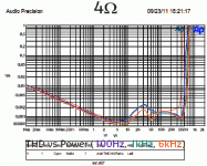
jmbulg: yes, except I used a lab supply here so output power on this graph is a bit optimistic. Otherwise the test conditions are the same.
david: The question hasn't been asked yet") For audiophile-grade DSP work consider the ever-on-the-horizon DLCP board. It'll come but the amount of work on the PC software end has been underestimated.
For audiophile-grade DSP work consider the ever-on-the-horizon DLCP board. It'll come but the amount of work on the PC software end has been underestimated.
tiki: yes, the 400 power stage is a bit friendlier in terms of how it transitions from soft to hard switching. I hope this improved behaviour makes up for the lower power output.
david: The question hasn't been asked yet
For audiophile-grade DSP work consider the ever-on-the-horizon DLCP board. It'll come but the amount of work on the PC software end has been underestimated.tiki: yes, the 400 power stage is a bit friendlier in terms of how it transitions from soft to hard switching. I hope this improved behaviour makes up for the lower power output.
Last edited:
jmbulg: yes, except I used a lab supply here so output power on this graph is a bit optimistic. Otherwise the test conditions are the same.
david: The question hasn't been asked yet
tiki: yes, the 400 power stage is a bit friendlier in terms of distortion.
The only question which remains is then: when ? for
 hopefully !
We're still targeting delivery in 2011. Keep your fingers crossed other work doesn't get in the way.
Then I know what I will put on my christmas list
HYPEX NCORE INQUIRY
Hello,
I few questions I would appreciate help with:
Please refer to the attached diagram of the proposed use of Hypex amplifiers to drive the Analog signal processorLinkwitzlab Orion.
The DIY audio version of the NCORE will apparently be around 400w-8 Ohms. The requirements for the Orion drivers are very low in comparison: 25 w (tweeter and midrange), 150-200w (dual woofers). What is is critical seemingly, is the "first watt" rather than high power.
Is power reduction via voltage rails recommended or possible?
Is the NCORE optimized for 400w and would it suffer sonically if the output was reduced?
With 400w, there is enough power to supply both woofers, but there is a question about preferred wiring configuration. Should the woofers be wired in parallel or in series?
Mr. Putzeys had alluded to designing an "ultimate" input stage for the NCORE. As someone with limited technical knowledge, this would be ideal, as opposed to having a detailed knowledge and ability to tweak the design. Can this be clarified any further at this stage?
Furthermore, I am unclear what sonic advantages OEM manufactures may have instituted with their own input buffers (Island Audio / Genesis Audio, etc.) for the earlier UCD series. Is this:
1. merely audiophile marketing hype
2. did they actually improve on the the Hypex design, or
3. tailor impedances of a standard Hypex input buffer.
Is there a way to tailor the NCORE input impedance relative to Analog Signal Processor (Active Crossover) for the different channels?
Are there any RFI issues with the NCORE to consider such as:
Proximity of amplifiers to each other.
Orientation and placement of PSU to amplifier.
Choice of chassis: Aluminium, wood, Plastic (Plexiglas / Perspex).
Proximity to Analog Signal Processor?
Will a DIY manual be released with tips and guidelines for the NCORE?
Thank you.
I also have a question, though more of a theoretical one.
How would an nCore design fare if the normal output filter would be replaced with high-frequency step-up transformer and some sort of notch filter, connected to an electrostatic driver, with AF feedback derived after the filter - although with different feedback ratio of course? Would that be possible?
It would be interesting if there would finally be an cheap way of powering DIY ESL headphones with good performance.
Nevod.
You cannot step up the audio output voltage of a class-D amplifier using a high frequency transformer. Although the PWM is switching at (say) between 250kHz and 350kHz, the spectrum of the signal goes all the way down to the lowest audio frequency.
I wish it was easy though, as I design PA/VA amplifiers providing a 100V output feed!
It is theoretically possible to achieve what you want by using a slightly different modulation scheme, together with full-wave synchronous 4-quadrant rectification at the secondary of the step-up transformer. This technique is used for lightweight 50/60Hz sine-wave invertors, but I do not know of any successful switching amplifier using a similar technique that can acheive the full audio range at low distortion.
@Fountainhead
Thx for posting the question here - I preferred it because I'm following this thread actively and anything I answer here saves me from having to answer similar questions.
With regards to reducing the power output of any class D amplifier. If you reduce the supply voltage, thus reducing the output power, the entire THD vs power graph shifts to the left by the same amount. For instance, the 25W distortion maximum of the NC1200 will move to 12.5W if maximum output is halved by dropping the supply voltage 30%. All class D amps have this behaviour. Given that distortion is so low I don't think it's a serious issue but strictly speaking you do not get a "better 1W amp" when you scale the supply voltage down.
The correct wiring of speaker units is not amplifier related. Loudspeaker designers tend to avoid series wiring because any antiphase motion of the woofers is not damped at all. I don't know how serious the problem is with modern units but subharmonic oscillations have been reported in the past.
The buffer design is finished. It is the usual two op amp arrangement except that the op amps are discrete and perform better than the current crop of "super chips". For the fanatics, the input stage is degenerated (with an inductor a la jensen to boost DC gain) and bootstrapped. The compensation is a T network around an ahuja transimpedance stage. Input bias current is compensated with a pot because any other method added non-linear capacitance.
Although the buffer on the UcD module is chip based and can be improved upon (as I'm doing with the NC400) the reason why VARs like to roll their own input buffer is mainly psychological. Uncharitably you could call it "audiophile hype" but one has to understand that they're taking a commercial risk buying their core technology from an OEM supplier. If a supply and a UcD module is all there is in the box they need something to differentiate them from direct competitors and from companies which sell similar products more cheaply.
A refreshing departure from this is Hexateq who make no bones about using the stock product because the chassis they put it in is drop-dead gorgeous and that alone is worth money.
Another reason why people may want to make changes is because they are after a specific sound (i.e. they don't even want the product to sound like others based on the same amp). They may call this sound "better" if they want but objectively the word is "different".
I should say that with industrial Ncore customers we're now insisting that if they add their own own buffer circuits, the measured performance of the completed amp should be as good as that of the stock unit. Of course this reduces the scope for moulding the sound, but that's what we want. We've seen at least one negative review of a UcD based product where the sound was substantially determined by an external input stage. Luckily for us the reviewer took care to point this out (having heard standard UcD circuits before). But it's not something we like to see happening with Ncore.
The input impedance of the buffer is high, and therefore suitable to be driven by anything. There's no need to tailor it. What you might want to tinker with is the gain. For this reason a gain setting resistor is located in a clearly marked and accessible place.
RF-wise, NCore modules behave at least as well as UcD modules, which are famous for their lack of interference problems. Essentially you construct your project as it suits you mechanically.
We try to provide fairly complete documentation. However, it's hard to foresee every question so occasionally we add stuff in response to support questions or forum discussions.
@Ouroboros: thanks
@Nevod: To clarify further, note that the output coil is an inductance in series with the output while a transformer is an inductance across the output. You can put feedback around a step-up transformer. The core size can then be slightly reduced because you need to design only for maximum output / lowest frequency before hard saturation.
Ouroboros,
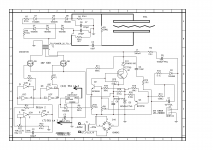
I believe the "adapter", which schematics I'm attaching here does something like that.
I don't remember exactly though how it works, have to dig though 50+ pages of forum for that. IIRC, it mixes 200 kHz square wave with input signal, provided from a normal power amp, and then runs it through a small step up transformer. THD is 1% at 200Hz, not suitable for higher frequencies.
Could you please explain what would be that modulation method?
Attachments
What Ouroboros is talking about is to have a 50% duty cycle source and a 4-quadrant synchronous rectifier equally running at 50% where the phase between the two square waves is varied. On average, somewhere on the planet someone is trying this method about once a year in an attempt to build a "one stage class D amp and SMPS" only to realise the thing still contains the same number of active devices and the same amount of ferrite. But it would rid you of the step-up.
Now something that I have been wondering about is why so many people want a class D amp to drive headphones with. You can build a HV amp for electrostatic headphones using devices no bigger than a TO92. No magnetics needed. If you use circuit boards for the stators you can integrate the amp.
Now something that I have been wondering about is why so many people want a class D amp to drive headphones with. You can build a HV amp for electrostatic headphones using devices no bigger than a TO92. No magnetics needed. If you use circuit boards for the stators you can integrate the amp.
Thanks Bruno, that's pretty much it.
The scheme I looked at basically takes the output of a normal PWM modulator and follows this with two async divide by two stages, one dividing on the rising edge of the PWM, and the other on the falling edge. The output from one of the dividers feeds the full-bridge output stage, while the output of the other divider controls the sync rectifiers. Both signals stay close to a 50% duty cycle, but have a varying phase shift between them.
Works well for a clocked open-loop system at 50Hz, but I'd like to see evidence that it could be made to work over the audio band. For 100V output class-D PA amplifiers it would be a useful technique.
Yes they were the DPC series (Digital Power Conversion). They were one of the first really powerful amps on the market using one rack space only.
At least in Switzerland they were not officially available. I am not sure wheter this was because of an EMC issue or maybe the lack of power factor correction.
Regards
Charles
At least in Switzerland they were not officially available. I am not sure wheter this was because of an EMC issue or maybe the lack of power factor correction.
Regards
Charles
Bruno, I would sure like to applaud your participation here in the DIY community. That seems to be a rare quality among professional audio designers.
The progress (e.g. input buffer) on the NC400 sounds fantastic. Are we rapidly approaching the "ultimate" amplifier in NCore? It sure seems to me that we are, at least in audible/measurable ways (i.e. what matters).
I'm planning for NCore to be my personal "ultimate" amplifier in any case
The progress (e.g. input buffer) on the NC400 sounds fantastic. Are we rapidly approaching the "ultimate" amplifier in NCore? It sure seems to me that we are, at least in audible/measurable ways (i.e. what matters).
I'm planning for NCore to be my personal "ultimate" amplifier in any case
Bruno, I have to step in and tell you how anxious I am about this product. I started to think that you've dedicated yourself completely to Grimm Audio and left Hypex for good. Happy to find the contrary.
I've been using a UCD180-based amp for about 5 years now and recently started to consider purchasing a Hypex SMPS as I got myself some rather hard to drive loudspeakers which make the current PS sound like it's reaching its limits sometimes. But I'm only happy to have looked here because I found about the NC and decided to wait until it's released. BTW one more vote for the 400W version (if the vote is still open).
I was curious about the form-factor and heat sink requirements. I might even order in advance a nice case for it
@FloridaBear: One can always imagine designing fancier output stages using the latest newest hyperwonderful power devices etc but for practical purposes the NC400 is going to be "the best I can do" for a while.
@MrPP The module is mounted flat and cooled through the base like the OEM series UcD modules. If you just bolt them onto the bottom of a metal case you've got enough cooling. Mounting them in an angled position requires an L bracket which we'll probably supply as well. The module takes up roughly the same size as the UcD400OEM but it's not exactly the same shape. I'm now revising the layout so more details remain up in the air.
@MrPP The module is mounted flat and cooled through the base like the OEM series UcD modules. If you just bolt them onto the bottom of a metal case you've got enough cooling. Mounting them in an angled position requires an L bracket which we'll probably supply as well. The module takes up roughly the same size as the UcD400OEM but it's not exactly the same shape. I'm now revising the layout so more details remain up in the air.
Last edited:
- Status
- Not open for further replies.
- Home
- Amplifiers
- Class D
- Hypex Ncore