Hello everyone, I am totaly new in Class D amplifiers, and I really want to bild D amplifier, something simple around 300-400W on 4 ohm load, without protection, really simple with ir2010, ir2110, irfp260, irf460 on example
I learned something on this forum obout D amp, but i need more") )
)
P.S Sorry for new thread, my english is really bad
I learned something on this forum obout D amp, but i need more
)P.S Sorry for new thread, my english is really bad
I would go for a IRS2092 design but beware of its touchy protection.
Decouple the IC and MOSFETs really well.
Keep the pcb layout very tight and loads of copper where you can.
Use IRFB4019 mosfets as these are low capacitance while still allowing 17 amps but use full deadtime.
I built one and was gobsmacked by its very wide bandwidth.
From very low to very high frequencies it was very good.
Last edited:
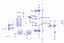
Look this, I was created few minutes ago. I want IR2110 and IRFP460 or IRFP260 because I already have this IC and power mosfets..
I looked the datasheets and examples of other people for IR2110 and I think that shematic is corect, can you chack this?
I dont have an idea for comparator (pin 10 and 12 of IR2110)!? I have shematic with TL071 and LT1016, but this LT is very expensive in my town, have you some other proposition, something simple and good?
I cretade PCB only for this what i have, it's small. Capacitors od 1000uF and 100nF of power rails are very close to power mosefets. everuthing is very close, but nice deployed and i think will be functionally.
which voltage do I need for 300 350W, i think +-60-65V, is this corect (like AB class or diferent)
Thanks and regards
Attachments
DJtosa2!
12V and 5V must be referenced to negative power supply rail! 12V must be decoupled by a good capacitor (for example 1 uF X7R), 5V is not really sensitive (there is almost no current). 100 ohm is toooo much for Rg. Forget IRFP460! IRFP260 is not a very good choice either, but can work.
GND pin of gate driver must be connected directly to source of low side FET!
Last edited:
Ok, thank you all for replay
I changed some elements, but i don't understand all because my english is very bad (only classes in high school)
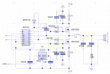
I removed 5V, pin 9 is also on +12V referenced to negativ supplay. I will add didoes between gate and out befor L for positive transistor and diode between gate and negativ rail for negativ transistor (1n4744). I dont understand that about bootsrap capacitor 330n, resistor and diode and gnd directly to what??? Sorry again
Wich transitor and voltage can use
Can anyone draw corect schematic for changes, sugestions on my schematic because i dont understand what sholud i do, I would be very grateful!
Again,thank you all. Regards
I changed some elements, but i don't understand all because my english is very bad
(only classes in high school)I removed 5V, pin 9 is also on +12V referenced to negativ supplay. I will add didoes between gate and out befor L for positive transistor and diode between gate and negativ rail for negativ transistor (1n4744). I dont understand that about bootsrap capacitor 330n, resistor and diode and gnd directly to what
??? Sorry againWich transitor and voltage can use
Can anyone draw corect schematic for changes, sugestions on my schematic because i dont understand what sholud i do, I would be very grateful!
Again,thank you all. Regards
Attachments
I have seen this being writen 100 times, I had no problems, calculated right for my fets and that about it, never a problemI would go for a IRS2092 design but beware of its touchy protection.
I have seen this being writen 100 times, I had no problems, calculated right for my fets and that about it, never a problem
I followed the datasheet to the letter yet it still just clicked permanently.
In the end the problem turned out to be the 10uf on the vcc rail.
I was getting glitches on the vcc line that put the 2092 into protection mode.
I put in a 47uF and that sorted the problem out.
One of the main problems I have spotted is many people want to use different mosfets and this is a minefield.
I eventually found the irfb4019 and this is a proper class d mosfet and that worked great and didnt cook the 2092 due to high capacitance.
Last edited:
there was no reply
Here I have done all the fixes that you told me
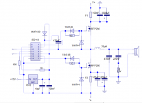
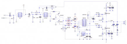
I atached two schematics, first is only IR2110 and second is total schematic of amplifier with LT1016 and TL071 (I can cope with 4070 very well, if someone have better solutions, I'd love to hear)
Please tell me is this corect,if it will work and what i must to change.
the most important is part of IR2110, I hope is coret now, because tomorow I will start PCB and I must know is all coret.
If someone thinks diferent, I would be grateful to coretct my schematic directly on it
Thank all of you my friends and Regards
Here I have done all the fixes that you told me
I atached two schematics, first is only IR2110 and second is total schematic of amplifier with LT1016 and TL071 (I can cope with 4070 very well, if someone have better solutions, I'd love to hear)
Please tell me is this corect,if it will work and what i must to change.
the most important is part of IR2110, I hope is coret now, because tomorow I will start PCB and I must know is all coret.
If someone thinks diferent, I would be grateful to coretct my schematic directly on it
Thank all of you my friends and Regards
Attachments
Why do you need a zobel network?
Not neccessary, but it makes fosc more stable.
true but it takes out valuable space...Not neccessary, but it makes fosc more stable.
regards,
savu
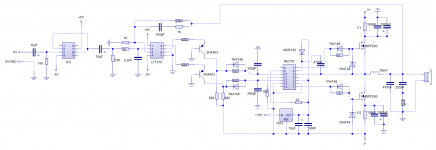
F2 is still not on the correct position. Level shifter must be dimensioned for higher amplification, and you must use much higher R and lower C for dead time.
IC3 does almost nothing.
Soory, can you explane me beeter, i dont understand you, what c and what r??
If I removed F1 and F2 it will be better, or not?
Others on schematic is corect or not? Can it work for 300 350W?
R and C mentioned above are for dead time ( for start use 2K7 and 100pF ).
Quoted from one datasheet: "A Zobel corrects the output loading to compensate for the rising impedance of the loudspeaker. Without a Zobel, the filter exhibits a peak response near the cutoff frequency."
So i think that Zobel network is desired - especially for self oscillating amps.
Quoted from one datasheet: "A Zobel corrects the output loading to compensate for the rising impedance of the loudspeaker. Without a Zobel, the filter exhibits a peak response near the cutoff frequency."
So i think that Zobel network is desired - especially for self oscillating amps.
Attachments
Last edited:
hvala zemljace, ponavljam jedan te isti post sto puta, nesto me sve zeza
zamenio sam ovo na semi sto si mi zaokruzio, menjam i izlane tranzistore, stvaljam irf540, valjda ce da izdrze tu snagu.
Jedino sto je ostalo nedoreceno jeste napon na koji to treba da napajam sve (da li je isto kao kod ab klase +-60V za nekih 280W) i 7812? Da li ce da izdrzi ako mu je na srednjem kraju recimo -60V na ulazu masa? da li je uopste projektovan za te napone i da li treba da okrecem polaritet elktrolita oko njega, smo jos to... PCB mi je zgusnutm vodovi debeli i kratki, sve je okruzeno vodovima kada ga zavrsim poslacu
Thank countrymen, I repeat one and the same post many times, something me all twisted
I replaced this on a semi that encapsulates me, change and specified in Article transistors, stvaljam IRF540, probably will to withstand the force.
The only thing left nedoreceno is the voltage at which it needs to feed all (is the same as in Class AB +-60V for about 280W) and 7812? Whether to stand if he is in the middle end of the say-60V at the entrance of the masses? if at all designed for these voltages and if you need to turn my polarity elktrolita about it, we still do ... PCB I zgusnutm lines thick and short, everything is surrounded by lines when I finish I will send
English please
dave

- Status
- This old topic is closed. If you want to reopen this topic, contact a moderator using the "Report Post" button.
- Home
- Amplifiers
- Class D
- Class D amplifier need schematic