I decide to start a new thread on this topic as the links are dead on the old one and the old thread title would not draw in new viewers to the topic I want to discuss which is the huge improvement in sound quality of a Class D amp that comes from using output filter coils with values that are much smaller than what would otherwise be dictated by the universally accepted "textbook" slope.
This is an interesting concept and supports my listening tests where the lowest tolerable coil value (I go as low as 3.5uH on each leg of my TK2050 amps) for the output inductor yields the best sound quality. Everyone blamed the change in sonics on the increased peak at 65KHz lifting the frequency response in the audio band but it is only a .5db increase at 20KHz so I knew that there must be another mechanism at work for the large improvement. So by accepting an out of audio band peak and some loss of efficiency at idle, rather than arbitrarily designing a 2nd order filter with a textbook slope, we will improve the sonics of a class D amp by using a lower inductance series coil in the output filter in a similar way to cranking up the bias of an AB amp further into class A.
.
PS. EMI emissions of the switching frequency are still very low with the smaller Wurth XXL coils at 3.5uH. Much lower than with Ferroxcube toroids wound to 8uH which leak quite a bit. Idle current is increased 25% with the lossy Wurths compared to the stock 20uH coils in the Shure 2X100 amp but the improvement in sonics is worth it.
.Hello DNA,
It's been discussed on this forum before, but you are seeing the curious effect on deadtime of the peak-to-peak current of the output inductor current of a class-d amplifier. As long as the output inductor current ripple is larger than the load current at the moment of switching, its current is in the right direction to force the output stage node voltage to begin slewing to the other rail immediately when both MOSFETs turn off at the beginning of deadtime (this is natural commutation - also known as soft switching). For larger load currents, slewing doesn't commence until the end of deadtime when the other MOSFET forces the voltage to change. Thus, unlike a linear class-b amplifier (where deadtime is at zero output) there are two deadtime zones at non zero load current (symmetrically spaced about zero)
This is an interesting concept and supports my listening tests where the lowest tolerable coil value (I go as low as 3.5uH on each leg of my TK2050 amps) for the output inductor yields the best sound quality. Everyone blamed the change in sonics on the increased peak at 65KHz lifting the frequency response in the audio band but it is only a .5db increase at 20KHz so I knew that there must be another mechanism at work for the large improvement. So by accepting an out of audio band peak and some loss of efficiency at idle, rather than arbitrarily designing a 2nd order filter with a textbook slope, we will improve the sonics of a class D amp by using a lower inductance series coil in the output filter in a similar way to cranking up the bias of an AB amp further into class A.
.
PS. EMI emissions of the switching frequency are still very low with the smaller Wurth XXL coils at 3.5uH. Much lower than with Ferroxcube toroids wound to 8uH which leak quite a bit. Idle current is increased 25% with the lossy Wurths compared to the stock 20uH coils in the Shure 2X100 amp but the improvement in sonics is worth it.
With the help of a parametric equalizer you can discover that 0.5dB in the 10khz to 20khz range in fact represent a dramatic change on perceived sound.
Then, what are you tasting? Apples or oranges? You can't be sure if you eat both at the same time.
Non scientific methods yield non reliable results.
High ripple current in the inductor has technical advantages, though.
Then, what are you tasting? Apples or oranges? You can't be sure if you eat both at the same time.
Non scientific methods yield non reliable results.
High ripple current in the inductor has technical advantages, though.
The nice thing in decreasing inductance is pushing crossover distortion up to higher powers without compromising efficiency much. This is very unlike class B, where xover dist happens at some miliWatts typically.
Wheather there is a peak in frequency response or not is a total blind guess anyway.
Or do you think an 8ohm speeker behaves anywhere close to 8ohm resistor at 10kHz to 20 kHz?
Wheather there is a peak in frequency response or not is a total blind guess anyway.
Or do you think an 8ohm speeker behaves anywhere close to 8ohm resistor at 10kHz to 20 kHz?
EQ
My Audio source for the last 5 years is a direct out modified DEQ2496 so I am quite familiar with the sound of simple frequency response changes. The improvement that is realized with the smaller values of inductance is something different than a simple top octave lift. More information is revealed across the entire audio band to the point where this has become my best sounding amp by far. Better than my former favorite TDA2750/ TIP amp and much better than the ever popular 3886 gainclone.With the help of a parametric equalizer you can discover that 0.5dB in the 10khz to 20khz range in fact represent a dramatic change on perceived sound.
Then, what are you tasting? Apples or oranges? You can't be sure if you eat both at the same time.
Non scientific methods yield non reliable results.
High ripple current in the inductor has technical advantages, though.
Even if the DC value of load current is very high (compared to the inductor ripple current), wont the voltage slew to the opposite rail due to the body-diode conduction during the dead-time? Am I making a mistake.
I don't understand how large ripple current can make the sound more pleasing. Aren't we interested only in the low frequency sound say upto 20kHz as anything above that would almost not make any difference to a human ear?
I don't understand how large ripple current can make the sound more pleasing. Aren't we interested only in the low frequency sound say upto 20kHz as anything above that would almost not make any difference to a human ear?
I decide to start a new thread on this topic as the links are dead on the old one and the old thread title would not draw in new viewers to the topic I want to discuss which is the huge improvement in sound quality of a Class D amp that comes from using output filter coils with values that are much smaller than what would otherwise be dictated by the universally accepted "textbook" slope.
.
This is an interesting concept and supports my listening tests where the lowest tolerable coil value (I go as low as 3.5uH on each leg of my TK2050 amps) for the output inductor yields the best sound quality. Everyone blamed the change in sonics on the increased peak at 65KHz lifting the frequency response in the audio band but it is only a .5db increase at 20KHz so I knew that there must be another mechanism at work for the large improvement. So by accepting an out of audio band peak and some loss of efficiency at idle, rather than arbitrarily designing a 2nd order filter with a textbook slope, we will improve the sonics of a class D amp by using a lower inductance series coil in the output filter in a similar way to cranking up the bias of an AB amp further into class A.
.
PS. EMI emissions of the switching frequency are still very low with the smaller Wurth XXL coils at 3.5uH. Much lower than with Ferroxcube toroids wound to 8uH which leak quite a bit. Idle current is increased 25% with the lossy Wurths compared to the stock 20uH coils in the Shure 2X100 amp but the improvement in sonics is worth it.
Even if the DC value of load current is very high (compared to the inductor ripple current), wont the voltage slew to the opposite rail due to the body-diode conduction during the dead-time? Am I making a mistake.
I don't understand how large ripple current can make the sound more pleasing. Aren't we interested only in the low frequency sound say upto 20kHz as anything above that would almost not make any difference to a human ear?
Very interested by this topic. I tweaked seriously a TK2050 kit from SURE and got it to a very satisfying point, especially compared to what it sound out of the box with the low cost passive components used. All caps are no low ESR ones, all possible values where changed to film type instead of chemical type, output inductors are high current types from WURTH, the power supply is a toroidal transformer with 10000 µF of filtering made with 1000µF caps in parallel etc...I also removed the polarity protection input diodes in serie with the power supply.
I stayed with the recommend output filter value of 10 µH for the inductor and 470 nF for the caps. The listening impression bothers me on SOME CDs. Let me explain : all drums have less impact, all cymbals sound too loud. Feels like there is really too much treble going out of these amps, on the other hand, despite their excessive level, they sound far much more metalic and therefore realistic than on other class AB amps from the market.
The theory show a theoretical flat response up to 20 Khz and even above with those filter values. But listening is in contradiction. Too brigh.
Anyone can help me to understand ? That really pisses me off as the amp is capabl of so much magic on the rest of the audio range, but that excess of treble really is a problem as it colours too much the sound ! How does lowering the inductor value help. It must be increasing the cutoff frequency and most probably adds noise that should be rejected by it, doesn't it ?
Speaker's not a resistor, as simple as that.
I'm aware of this
") But the TK2050 has a feedback. So like any other amplifier, the output voltage is input x gain.
But the TK2050 has a feedback. So like any other amplifier, the output voltage is input x gain.My Cabasse speakers have a very flat response at constant input voltage from 20Hz up to 20 Khz, whatever the impedance change involved.
So I'm wondering how I can hear so my treble when the sampe speakers don't generate them with other linear amplifiers with feedback just like this Tripath.
But the TK2050 has a feedback.
Are you sure? After the filter?
Are you sure? After the filter?
Unfortunately no, due to the nature of the way the IC works, the FB is before the filter, hence its importance
I have seen a company getting rid of this problem because their own made class D amps have FB after the filter, but I believe it is not possible with Tripath chips (I beliebe they would have done it otherwise)LC filter is outside of feedback loop, so quite possibly the filter amplifies above 10kHz on real speakers.
So I'm wondering how I can find this out. Some problems can no be seen with a frequency generator and a fixed sinewave at input and an oscilloscope at speaker connection. Maybe worth trying to make sure
As my filter network is L and C, and that C is easier to change than L (because it is SMD type), maybe it is worth increasing a bit C (currently 470 nF like TRIPATH App note). L is 10 µH
thank you
A bigger capacitor causes more trebble! (I know, it's strange.)
Try a 1.5 uF cap with a series 6R8 resistor!
Bigger, more treble ?
As C is between signal and ground, should not be ?
Do you mean replacing the 470 nF by your recommend R+C network ?
Have you tested / measured to see result ? (or rather to hear
)Keep the capacitor to ground and add another RC to ground. 6R8 is a good starting value, but you may end up with different value. As soon as you have generator and scope connected try tuning the system for flat voltage response at speaker terminals manipulating resistor value. Remember to use high wattage resistor, a quarter of amplifier power rating is big enough.
softer coils
Perhaps now you are finally hearing everything your source is putting out. If you want more of a relaxed, filtered, tubey sound, you can take out the Wurth coils and use some of the type 2 toroids which can be purchased in a 10uH value on ebay.I stayed with the recommend output filter value of 10 µH for the inductor and 470 nF for the caps. The listening impression bothers me on SOME CDs. Let me explain : all drums have less impact, all cymbals sound too loud. Feels like there is really too much treble going out of these amps
I have bought a old nice PHILIPS 100 Mhz scope together with a WATEKEK signal generator as I could not stand anymore to rely just on what I head (too much treble) and be unable to confirm by measurements.
Guess what ?............
What I hear us ABSOLUTELY confirmed by measurements
I inputed the WAVETEK signal to the TK2050, loaded it with my CABASSE speakers and adjusted the output swing to 2 Vpp at 500 Hz, assuming that the filter doesn't affect this frequency.
I started to increase the frequency and found out the beginning of the voltage increase at around 20 Khz.
At 30 KHz, the voltage at the speaker input is no more 2 Vpp but 2.5 pp !
At 40 KHz, I'm over 3Vpp
At 65 KHz, I'm at the max of this voltage increase with an output above 6 Vpp !!
I checked the input voltage, it is absolutely flat so this comes from the amplifier and / or the filter.
Based on this, I wonder how it is possible that NO ONE on any blog ever heard this excess of treble. TRIPATH recommend filter with L=10µH and C=470nF is not giving a flat output at all !
Does anyone on this blog have a sinewave generator and a scope to check on his own system if he finds the same frequency overshoot ?
In all case now I know what I hear is real !
Thanks for your inputs
16ohm?
Must be your speakers are closer to 16ohm than to 8.
.
Must be your speakers are closer to 16ohm than to 8.
.
I have bought a old nice PHILIPS 100 Mhz scope together with a WATEKEK signal generator as I could not stand anymore to rely just on what I head (too much treble) and be unable to confirm by measurements.
Guess what ?............
What I hear us ABSOLUTELY confirmed by measurements
I inputed the WAVETEK signal to the TK2050, loaded it with my CABASSE speakers and adjusted the output swing to 2 Vpp at 500 Hz, assuming that the filter doesn't affect this frequency.
I started to increase the frequency and found out the beginning of the voltage increase at around 20 Khz.
At 30 KHz, the voltage at the speaker input is no more 2 Vpp but 2.5 pp !
At 40 KHz, I'm over 3Vpp
At 65 KHz, I'm at the max of this voltage increase with an output above 6 Vpp !!
I checked the input voltage, it is absolutely flat so this comes from the amplifier and / or the filter.
Based on this, I wonder how it is possible that NO ONE on any blog ever heard this excess of treble. TRIPATH recommend filter with L=10µH and C=470nF is not giving a flat output at all !
Does anyone on this blog have a sinewave generator and a scope to check on his own system if he finds the same frequency overshoot ?
In all case now I know what I hear is real !
Thanks for your inputs
Hi Scott
in fact my speakers are 4 ohms nominal, 2 ways.
But the impedance of the tweeter is above 20 Ohms at 20 Khz from its specification
I hesitate between two options
- add an RC compensation network (R and C in serie, the whole in parallel to the load)
- tune the L and C value to find flat response
any thoughts ?
Gaël
Hi,
if the amplifier has a flat response at least up to 16R, then it is convenient not to change anything.
if amplifier has a gain at the end of the band (no matter that is outside the audio band, because they reflect the harmonic sub-band) and this worsens the hearing of high frequencies.
Then LC should fix first and then fitting works with small RC.
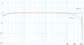
Is not good change only L or C and try to listen. pic show poor result (changed only C)
Regards
if the amplifier has a flat response at least up to 16R, then it is convenient not to change anything.
if amplifier has a gain at the end of the band (no matter that is outside the audio band, because they reflect the harmonic sub-band) and this worsens the hearing of high frequencies.
Then LC should fix first and then fitting works with small RC.
Is not good change only L or C and try to listen. pic show poor result (changed only C)
Regards
Attachments
- Status
- This old topic is closed. If you want to reopen this topic, contact a moderator using the "Report Post" button.
- Home
- Amplifiers
- Class D
- High bias class D