Here you are. Please comment.
Sorry, I am late here.
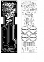
Dear opor, With reference to the thread no. #1094. Is the PCB incomplete? because when I opened it in protel it shows two unrouted connections.
Last edited:
its not made for BJT'sHi all
anyone use IR2110 with BJT(output)
RGDS
MANOJ
Hi CPX
for 13.8A OCP, MOSFET should be 28A rated for 1us and 56A for 1sec.
RGDS
MANOJ
As i said i am NOT using your protection schematic,but thank you for your feedback
") .
.its not made for BJT's
so why they are using totem pole (BJT)
they do, but not as an end drivers. if they were, you would need to feed the base with current, which would run out before the end of the period, unless your upper boost capacitor was big. But then IR would produce too much heat. It has to be IGBT or FET for end transistor and even then, input capacitance can't be off the chartsso why they are using totem pole (BJT)
I have new problems and i need your help once again.
a)When using both my amplifier modules I have huge rf interference resulting in high frequency noises.Isolating suplies doesn't help.I have to efectively put the amplifiers 15 cm apart for them to work good and that is not acceptable.They are at least 30 khz different in switching frequency.
b)Also i can not use one heat sink since this increases ten fold these perturbations and i can see huge common mode noise.
Syncroning switching frequencies by injecting square wave signals into negative input thought a capacitor and resistor solves some first case interferences but increases distorsions alot especialy at higher modulation so this approach can not be used and anyway it doesn't solve case b).
In case b) the heat sink injects hight frequency noise into ground because there is at least a 70pf capacitance between one transistor and heat sink and also acts like emiting antenna fueld by any diffrence betwhen switching outputs between chanels since these will never be perfectly sincronized even with exactly the same frequency and phase because input signals are not identical.But i see lots of solutions with only one heat sink and multiple channels and they work ok so i am missing something.
Thanks for any ideea you may have...
and i need your help once again.a)When using both my amplifier modules I have huge rf interference resulting in high frequency noises.Isolating suplies doesn't help.I have to efectively put the amplifiers 15 cm apart for them to work good and that is not acceptable.They are at least 30 khz different in switching frequency.
b)Also i can not use one heat sink since this increases ten fold these perturbations and i can see huge common mode noise.
Syncroning switching frequencies by injecting square wave signals into negative input thought a capacitor and resistor solves some first case interferences but increases distorsions alot especialy at higher modulation so this approach can not be used
and anyway it doesn't solve case b).In case b) the heat sink injects hight frequency noise into ground because there is at least a 70pf capacitance between one transistor and heat sink and also acts like emiting antenna fueld by any diffrence betwhen switching outputs between chanels since these will never be perfectly sincronized even with exactly the same frequency and phase because input signals are not identical.But i see lots of solutions with only one heat sink and multiple channels and they work ok so i am missing something.
Thanks for any ideea you may have...
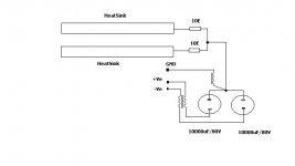
hi cpx
10E with 2KPf parallel connected to GND and use small ferrite with 3turns connected from main GND to signal gnd noise will reduce.
cpx my old thread i mentioned ground plane is creating problem for me but nobody supported.avoid ground plane on MOSFET & Filter side OR do not use ground plane,its my opinion other side i don't know.
RGDS
Manoj
triell amp 3200 d
triell dclass anyone have its schematic pcb can be made but some parts
can not be seen clearly
warm regards
andrew lebon
triell dclass anyone have its schematic pcb can be made but some parts
can not be seen clearly
warm regards
andrew lebon
Attachments
hi cpx
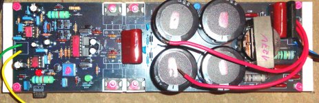
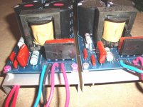
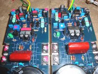
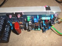
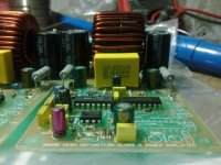
my new design (you said its BAD PCB Design) i used yellow/white core with 30Turns 16SWG wire and 3x IRFP240, core temp. is 35-38deg.c MOSFET Temp. 38-40deg.c low EMI
tested voltage with +42V,-42V DC load 5E 50W resistor stead @full volume for 1hr.
i never taken THD measure,DC offset is -18mV to -24mV.
everyone said IRFP240 & yellow/white core not good for class D. My curiosity is practically what happen in this components
IRF240 is Qg is affordable rate clamp diode not good solving this connect good diode externally,my way like this
RGDS
Manoj
triell dclass anyone have its schematic pcb can be made but some parts
can not be seen clearly
hi andrew
i think its your first schematic used with 2x IRFP250
RGDS
Manoj
- Home
- Amplifiers
- Class D
- UCD 25 watts to 1200 watts using 2 mosfets