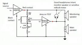
This is very good way to test your amp.
Use this schematic and try it..
Now I will send text and explonation from dr.Borivoje Jagodic, engineer from my contry.
*Sorry for bad english but this text is from google translate and copy-paste from dr. Boras web site") .
.
"Testing distortions without special equipment"
(HAFLER differential test)
Use this schematic and try it..
Now I will send text and explonation from dr.Borivoje Jagodic, engineer from my contry.
*Sorry for bad english but this text is from google translate and copy-paste from dr. Boras web site
."Testing distortions without special equipment"
(HAFLER differential test)
Attachments
Ok...but i need someone with good ears to make my distosion tests since i have no distortion analyser.
I can hear different levels of distorsions going from no load to 2, 4 and 8A load especially on frequencies<100hz.
If you have a good sound card, then you can use your computer as signal generator, and also distortion meter. You just need to divide amp output carefully, not to cause any harm!
Even if you have no good soundcard, it will be sure enough to determine the 0,1%, 1% and 10% point.
So far I can say that your unit is going in the wrong way, it has serious switching issues. I reccomend you to try an other ones unit, like dzony's. Me and he also had only minor noise problems, and no distortion problems.
Lorylaci,why do you thing it has serios switching issues?What is that you see wrong in it?
Dzony988 thanks for your ideea.
Anyway i will make sound card distorsion tests or the HAFLER differential test only after i will hear no distorsion with my headphones..
Dzony988 thanks for your ideea.
Anyway i will make sound card distorsion tests or the HAFLER differential test only after i will hear no distorsion with my headphones..
Last edited:
If you want i can send you both sides and you can try it.
One mount ago maybe two, noise for me was end of world but, since I work at night club, many convencial amp like LEM, Crest, LTO, even one Dinacord have noise when Volume pots are on maximum. Ofcourse this is very little, when I come very close to speaker, like on my amp but when music plays nobady cant hear enything.
I discovered that my amp dont have a noise at all on 8 ohms load, but thats menas nothing because 8 ohms load for me dont exist)))). For PA I onlu use 4 and 2 ohms, because one amp "pushl" 4 x 15" high pass and second 2x15" subwoofers on one chanel and 2x18" subwoofers on second chanel.
One mount ago maybe two, noise for me was end of world but, since I work at night club, many convencial amp like LEM, Crest, LTO, even one Dinacord have noise when Volume pots are on maximum. Ofcourse this is very little, when I come very close to speaker, like on my amp but when music plays nobady cant hear enything.
I discovered that my amp dont have a noise at all on 8 ohms load, but thats menas nothing because 8 ohms load for me dont exist
)))). For PA I onlu use 4 and 2 ohms, because one amp "pushl" 4 x 15" high pass and second 2x15" subwoofers on one chanel and 2x18" subwoofers on second chanel.
I can hear my amplifier noise starting from 50 cm to the speaker in a quiet room...it is just like the noise generated from tda7294 with gain 30,but my class AB receiver has much lower noise on minimum volume..only hearable with ear glued to the tweeter and only at night,anyway my internal ear noises are louder so at 1 meter i can hear only them...
Also distorsions are not obvious..i can only detect them with test tones...the noises coming from reflex tubes and resonances in my room are much worse..i just have the craving in finding out how i can lower them...
Decreasing dead time reduces distorsions dramatiacly at <100 hz but 300-400mA idle current is to much for me..
Tl074 is very noisy..try something else...i am using lm833 but are much better opamps out there...
Last edited:
Lorylaci,why do you thing it has serios switching issues?What is that you see wrong in it?
Dzony988 thanks for your ideea.
Anyway i will make sound card distorsion tests or the HAFLER differential test only after i will hear no distorsion with my headphones..
Because your extreme snubbers. Normally, much much smaller snubbers are enough. I used the original 100p 100r, and there was minimal ringing.
There is no really point measureing your unit, until you make an unit which has acceptable switching behavour.
I don't know what is exactly wrong with yours, but its definetly not a go. If I were there, and could look at everything, see the exact test setup, could point ot things, but so far I would vote on a complete rework.
The problem is i do not know what to rework,i have ground plane,ultra small distances in critical areas,bypasing..etc,i am pu
For example Dzony988 has a power ground loop around lm311 which isn't good at all...nevertheless he has low distorsions..,others have long feedback wires(Including the author) and also are heapy with their setups..so i am puzzled...
Dzony988 i do not know any quad ultra low noise opamp...all that i know are single or double..
TL074 is quad op amp low noise (4 x TL071 or 2x TL072) I dont have problems with noise with TL074.
Do you know any quad op amp like TL074 with pins compatibile to it, low noise ofcourse?
Thanks
TL084 has 20% less noise than TL074. But the differences are totally inmeasureable with normal instruments. High-tech stuff (and even high-tech room) is needed to measure that.
So don't blame opamps for noise, there are lots of other stuff.
CPX could you make a photo of your test setup? That could help, maybe some of us could spot a bug. (everytime there something doesnt work, I always wish to find something that I screwed up...)
If you page back, you can see my layout, which I must confess not the best, but I had low noise and low distortion.
Hm..strage..increasing gain at the buffer increases distorsions at the same load in amps!!!!!!!
In my head that means noise from switching stage gets somehow into buffer input....,but since i have 1 nF on positive input i thought that the negative feedback is where the noise comes in..so i put a 1 nF capacitor between buffer output and in- and it increased distorsions!!!!!!!!...i do not understand what is heapening...there is something wrong at the input.feedback stage...but what???
no snubbers at 4A load..huge distorsions...
100pF,4.7 ohm subber at 4A load
1nF,4.7 ohm snubber at 4A load
setup:
In my head that means noise from switching stage gets somehow into buffer input....,but since i have 1 nF on positive input i thought that the negative feedback is where the noise comes in..so i put a 1 nF capacitor between buffer output and in- and it increased distorsions!!!!!!!!...i do not understand what is heapening...there is something wrong at the input.feedback stage...but what???
no snubbers at 4A load..huge distorsions...
An externally hosted image should be here but it was not working when we last tested it.
100pF,4.7 ohm subber at 4A load
An externally hosted image should be here but it was not working when we last tested it.
1nF,4.7 ohm snubber at 4A load
An externally hosted image should be here but it was not working when we last tested it.
setup:
An externally hosted image should be here but it was not working when we last tested it.
An externally hosted image should be here but it was not working when we last tested it.
An externally hosted image should be here but it was not working when we last tested it.
An externally hosted image should be here but it was not working when we last tested it.
Last edited:
Hm..strage..increasing gain at the buffer increases distorsions at the same load in ampers!!!!!!!
In my head that means noise from switching stage gets somehow into buffer input....,but since i have 1 nF on positive input i thought that the negative feedback is where the noise comes in..so i put a 1 nF capacitor between buffer output and in- and it increased distorsions!!!!!!!!...i do not understand what is heapening...there is something wrong at the input.feedback stage...but what???
no snubbers at 4A load..huge distorsions...
An externally hosted image should be here but it was not working when we last tested it.
100pF,4.7 ohm subber at 4A load
An externally hosted image should be here but it was not working when we last tested it.
1nF,4.7 ohm snubber at 4A load
An externally hosted image should be here but it was not working when we last tested it.
setup:
An externally hosted image should be here but it was not working when we last tested it.
An externally hosted image should be here but it was not working when we last tested it.
An externally hosted image should be here but it was not working when we last tested it.
An externally hosted image should be here but it was not working when we last tested it.
What type of inductor are you using? It can hardly be seen.
The green thing is DIY photo-resist resin? Some of those are measureably conduct at high frequency. (and some them even arc at high voltage transients)
I got back to page 144, to see your layout, and from that the feedback path, and the comparator connenction seems totally different from the original schematic. Could you draw the exact schematic, of just that part?
I am using micrometals t106-2 core wound up to 30Mhenry multilayer..i wound one 20uH one layer but i dint change distorsions..the lower inductance increased 100 hz noise..
The green thing is permanet marker,the board is made with PNP.
The board was made for for ionut_gaga simetric feedback scheme..but i am using this now:
The green thing is permanet marker,the board is made with PNP.
The board was made for for ionut_gaga simetric feedback scheme..but i am using this now:
An externally hosted image should be here but it was not working when we last tested it.
I am using micrometals t106-2 core wound up to 30Mhenry multilayer..i wound one 20uH one layer but i dint change distorsions..the lower inductance increased 100 hz noise..
The green thing is permanet marker,the board is made with PNP.
The board was made for for ionut_gaga simetric feedback scheme..but i am using this now:
An externally hosted image should be here but it was not working when we last tested it.
So the feedback seems fine.
It is interesting, because I never had 100Hz (50Hz) noise with so this is strange. The opamp before the comparator works as a buffer and for protections?
Have you tried feeding input, after this buffer stage? So as in original schematic. (into the opamp through with DC blocking capacitor, input resistor, input RF stoping resistor and capacitor)
Buffer op amp was also for under voltage lockout but i made a mistake..that will be corrected in new board..
I connected input after buffer and changed feedback shunt resistor to 330 ohm,hiss is huge now(60x gain) but 50 hz distorsions have decreased alot... still not perfect but a big improvement...thanks for the ideea...i do not know why the buffer distorts...
I am going to bed now..to tired...beautifull dreams for you too!!!
Last edited:
Ok..i connected input after buffer and changed feedback shunt resistor to 330 ohm,hiss is huge now(60x gain) but 50 hz distorsions have decreased alot... still not perfect but a big improvement...thanks for the ideea...i do not know why the buffer distorts...
I am going to bed now..to tired...beautifull dreams for you too!!!
Are you setting the gain of the input buffer to match 0db input ? If not you are going to get a lot of distortion. You dont need a gain of 60. A gain of 10 is more than sufficient. I designed a similar amp.
No..no..that gain was at the comparator only for testing without buffer...
I didnt use any gain at the comparator on my amp. I didnt use positive feedback (hysteresis) either, it worked fine as a simple comparator.
Of course there is gain at the comparator...there is 28x in lorylaci's schematic and around 40x in the original schematic..to have no gain you need R10(my schematic) to be infinity..and in that case you are limited with output peak voltage to op voltage-1 ..so around 2 volts in the original schematic..
- Home
- Amplifiers
- Class D
- UCD 25 watts to 1200 watts using 2 mosfets