hi dclass
greetings everybody any substitute for in5819 better to build this
amplifier and find out how it works started it only high speed diode in5819
hard toget
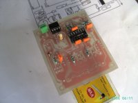
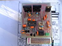
Nice PCB andrewlebon !
hi
greetings reading spanish forum ic shown on pcb is ir2113 schematic shows
it ir2110 is it possible on amplifier built by tatacom
1 any substitute for diode in5189
2 details of coil 33uh wire diameter no of turns core diameter
thanking you
andrew lebon
My nickname is Tacatomon XD

I attest that the amplifier works at first, provided they are armed with dedication and with premium components.
There are some known problems:
The output coil heats up, and that's a fact, is filtering high-frequency component. Typically for lower voltages of +-60VDC coil core outdoor air is hot work, but will not burn unless I do not step ...
For higher voltages, ventilation is essential. Yet the use of an iron powder core as did a colleague. Better safe than sorry.
There are some problems with DC at the output. I do not really showing anything ... Use an air core coil improvised and it works fine. It's several threads and I made based on a website called Pronin or something. I made several prototypes, the first was from a single strand of copper and it showed over the fidelity of sound output. The output mosfets were lukewarm, at that time used a voltage of about +-50VCD. These problems may be caused by the quality of components, especially the comparator, the opinions that have emerged in the Spanish forum ForosDeElectrónica, improper positioning of the coil ...
It really is a very simple design but effective way. They may say it has some technical points as commented outdated pages back, but
hi tactomon
greetings thanks for your feedback since you have made it please
can you share all problems encountered while making this amplifier
1 how reliable is this amplifier and how powerful does it really have 1200 watts
2 voltage supply used the maximum you have tried on this amplifier
3 procedure for powering up amplifier first on
4 silver mica 330 pf very hard to get used 330 pf 1000 volts ceramic is it ok
hoping you will share your experince of building this amplifier with d class forum
thanking you
andrew lebon
Well ...
The output power is given by the supply rails ... More or less something like sqrt (W * 2 * Rload) The maximum current is I = V / R and the maximum dissipation in the mosfets will PDmos = I * I * Rdson / 2 (Each mosfet works half the time! !).
With these calculations and we get an idea of how much power we can get. Actually the limit is given by the mosfets that we find in the market. 11.250 W are possible according to the author. It is "acceptable" one branch feeding +-300VCD. Would have to find those mosfets to withstand the voltage and current involved, about 38A RMS ... But most of you know that reaching those powers is absolutely deadly where you may be ...
The most with which I have tried is +-90VCD while empty. + In-charge are as 86VCD. I had some problems to start with this diet. At the start of testing this dangerous voltage, a branch of the amplifier up to 106VCD and the other was down to 82 ... As I said the creator of the amplifier, there are several causes for what happened to me.
1 .- Very low capacitance reservation. I used 8000uF.
2 .- the threshold voltage MOSFETs. He used the IRFP250
Perhaps I joined the two problems that caused the imbalance of voltage. Part of the explanation is that I was a part of the energy source is burned in the speaker, but some returned to the source through the topology of this amplifier. Being the limit voltage mosfets tend to act like diodes Zeners, limiting the voltage to 100V and making a branch is "Overload" voltage "return" ...
To start the amplifier ... Simple. After assembling, the coil assembly and verify the correct assembly of the amplifier (Armed with the power components for a 400W/4Ohms), proceeded with a power source with a symmetrical 50VCD 4A, a 100W lamp connected in series everything and put a small speaker to test the sound. At first made the pop classic, but it's a bit worrying, because sometimes you hear the sound as if it were shorted out and spend the entire DC to the speaker, but no, just a moment and gave me only the firsts. A bit of audio, well, a load of 4 ohms, well, that this output mosfets ... Warm, such coil, hot, burning to the touch .. Sound loud and clear. Not very noticeable switching noise. In the piezoelectric tweeters you will hear a slight hiss closer ear to these ... From there on out, is very quiet and you can do it with the appropriate cables and a good position of the coil.
For the latter, I used multilayer ceramic 330pF 100V
The photos, you already saw her ¬ ¬
Only there's more
Login to a private Photobucket.com album
Greetings!
The output power is given by the supply rails ... More or less something like sqrt (W * 2 * Rload) The maximum current is I = V / R and the maximum dissipation in the mosfets will PDmos = I * I * Rdson / 2 (Each mosfet works half the time! !).
With these calculations and we get an idea of how much power we can get. Actually the limit is given by the mosfets that we find in the market. 11.250 W are possible according to the author. It is "acceptable" one branch feeding +-300VCD.
The theory is fine, but you ignore too many facts. You ignore all of the switching losses (turn on, turn off, and the most important: diode loss), which can be much more then the conduction loss. You ignore the not perfect cooling. You don't seem to be aware the fact that a hot FET has a 2.5 times higher Rdson then the nominal. You don't provide safety margins.
Have you measured the output power (with dummy load and sine wave)? The paper can bear anything, but practice is different!
hi dclass
greetings everybody any substitute for in5819 better to build this
amplifier and find out how it works started it only high speed diode in5819
hard toget
It's not in5819, but 1N5819. In this circuit it can be substituted with almost anything (fast, small diode), eg. 1N4148.
The theory is fine, but you ignore too many facts. You ignore all of the switching losses (turn on, turn off, and the most important: diode loss), which can be much more then the conduction loss. You ignore the not perfect cooling. You don't seem to be aware the fact that a hot FET has a 2.5 times higher Rdson then the nominal. You don't provide safety margins.
Have you measured the output power (with dummy load and sine wave)? The paper can bear anything, but practice is different!
There is also the fact that MOSFETs require about 3.5 volts to turn them on so you lose 7 volts in total to the output.
You also lose 40% of your power as heat in the heatsink.
a branch of the amplifier up to 106VCD and the other was down to 82 ... As I said the creator of the amplifier, there are several causes for what happened to me.
1 .- Very low capacitance reservation. I used 8000uF.
2 .- the threshold voltage MOSFETs. He used the IRFP250
These are false reasons, reflecting no knowledge about ClassD amps. The reason is DC offset on output. Against it a capacitor (22 uF) in series with the lower resistor of the feedback can help. There is a better, but a little more complicated solution too.
hello I made myself this amp and do not work!
An externally hosted image should be here but it was not working when we last tested it.
which mosfets do you use ?
another people say its working very well, Im confused
I dont have build and test
but in my experience class D is not so good sounding in mid and High frequency in premium sound system for finest sound compare to class AB and class H
In low quality sound system class D is ok and working very well
have test last 2 years different commercial Class D amplifier including powersoft K series and there is not big different in sound only in price for brand
Class D is more energy efficient in power consumption but a good designed Class H output stage does Class D kick out of the job
- Home
- Amplifiers
- Class D
- UCD 25 watts to 1200 watts using 2 mosfets