Since the output coil was so small that I had to wrap around such a small. Could it be that the IR2110 burn? 150uh
Attachments
1000W class D car amp project (withPCB)
YouTube
Nice work!! can you share a pcb?
thanksNice work!! can you share a pcb?
pcb files shared on video comment section
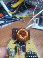
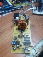
Hi, i made by this circuit
It's my first class D and it look a bit tricky") Im using IRF540Z, 22ohms+1n4148, mur120 at ir2110, t106-2 37turns with 1mm wire+ 0.47uf cap. +/- 27v 4ohms load. First try was good ,worked good, sound clear, mosfets maybe ~40-45C, no heatsink, ir2110 with small heatsink ~40-45C too,fsw ~280khz. But after week, on low volume ~5% mosfets overheated, i think got parasitic oscillation, couse input cable(not shielded) was crossed with output. After change to other pair of IRF540Z fsw dropped to ~220khz (according to multimeter), ir2110 cold, mosfets heating with heatsink ~80cm2 plate in a minute over 50C at idle. What changed? Any suggestion? Thanks
Im using IRF540Z, 22ohms+1n4148, mur120 at ir2110, t106-2 37turns with 1mm wire+ 0.47uf cap. +/- 27v 4ohms load. First try was good ,worked good, sound clear, mosfets maybe ~40-45C, no heatsink, ir2110 with small heatsink ~40-45C too,fsw ~280khz. But after week, on low volume ~5% mosfets overheated, i think got parasitic oscillation, couse input cable(not shielded) was crossed with output. After change to other pair of IRF540Z fsw dropped to ~220khz (according to multimeter), ir2110 cold, mosfets heating with heatsink ~80cm2 plate in a minute over 50C at idle. What changed? Any suggestion? Thanks
An externally hosted image should be here but it was not working when we last tested it.
It's my first class D and it look a bit tricky
Im using IRF540Z, 22ohms+1n4148, mur120 at ir2110, t106-2 37turns with 1mm wire+ 0.47uf cap. +/- 27v 4ohms load. First try was good ,worked good, sound clear, mosfets maybe ~40-45C, no heatsink, ir2110 with small heatsink ~40-45C too,fsw ~280khz. But after week, on low volume ~5% mosfets overheated, i think got parasitic oscillation, couse input cable(not shielded) was crossed with output. After change to other pair of IRF540Z fsw dropped to ~220khz (according to multimeter), ir2110 cold, mosfets heating with heatsink ~80cm2 plate in a minute over 50C at idle. What changed? Any suggestion? Thanks 1000W class D car amp project (withPCB)
YouTube
The video is unavailable 😬😬
Nice amp where are the pcb files??
+/-90V gives a total of 180V so try 1800V just to be safe... Or you might notice that VB is derived via a diode from the IC supply, VCC, when the lower mosfet is on. Pick a capacitor with a voltage rating higher than VCC. Something like 25V. Make sure the VRRM of the diode is sufficient >180V. UF4003 or higher.
+/-90V gives a total of 180V so try 1800V just to be safe... Or you might notice that VB is derived via a diode from the IC supply, VCC, when the lower mosfet is on. Pick a capacitor with a voltage rating higher than VCC. Something like 25V. Make sure the VRRM of the diode is sufficient >180V. UF4003 or higher.
thank you for your help
Me again
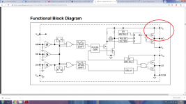
So I build my new pcb from below schematic with some changes:
Class D amp.jpg - Google Drive
Unfortunately I blew my 2 mosfet at the same time with no input signal and even no heat on mosfets
So my question is here, Can I test this amp circuit before installing the mosfets to make sure LM311 and IR2110 are working normal?????
I have a 20MHz analog oscilloscope that I could work with
Thank you in advance
I've just found this thread and am sceptical of the basic circuit - there seems to be no provision for deadtime generation, and nothing to stop HIN/LIN going more positive than Vdd at powerup, which will blow the chip. My feeling is there's going to be a lot of very hot MOSFETs and sudden failures.
There are lots of MOSFET high low gate driver chips available, many with deadtime generation, some with programmable deadtime generation.
The differential pair circuit seems to be configured to generate about 11V across the output resistors to feed HIN/LIN, so as the current steers between the two devices there will be a crossover point with about 5.5V on HIN and LIN simultaneously.
LIN and HIN are 3.3V logic compatible inputs, so will register HIGH from about 2V up, so both MOSFETs are pretty much guaranteed to be hard on simultaneously, wasted lots of power heating the MOSFETs and generating lots of EMI and output distortion come to that.
Shoot-through can also cause sudden failure of the MOSFETs too.
(Assuming I've understood the function of the circuit of course.)
Substituting the FAN7380 for IR2113 might be worth considering, it has shoot-through prevention with 100ns deadtime and is also 600V rated.
The original circuit using 300+300 supply and a 600V absolute max driver chip is a complete face-palm, 600V absolute maximum is totally not the same as 600V working voltage!
Guys when I connect the amp to power supply and connect the speaker to the output I can not hear any hiss or hum coming out of the amp(here amp is drawing 30 mA in each channel) but as soon as I fed the music to the input the sound is kind of distorted and when I cut the music and short circuit the input, amp still draws about 200mA from each channel and there's a hiss present in output
in this situation if I disconnect the output coil for a few seconds and connect it again the hiss goes away and the amp rail's current goes back to 30mA
So what do you think is the problem here?
in this situation if I disconnect the output coil for a few seconds and connect it again the hiss goes away and the amp rail's current goes back to 30mA
So what do you think is the problem here?
Hey guys
So looks like nobody's here
I'll appriciate if anybody could help me with this amp
I manage to run this amp after a lot of mosfet failures and now the sound is kind of good but not great
I noticed that the negative rail draws way more current than positive one. when I increase the output power to about 100w, the current draws from negative rail is about 2 A while the positive one only consume 0.6 A
is this normal due to the supply of IR2110 by negitive rail?
Also I can't get a clear upper wave form in the output as you could see in the video below:
YouTube
PS: I'm using this schematic
image.png - Google Drive
Thanks in advance
- Home
- Amplifiers
- Class D
- UCD 25 watts to 1200 watts using 2 mosfets