Has anyone done anything with quadrature oscillators fed to an XOR gate for a PWM? After messing with various triangle generators and different comparators I thought maybe another method, aside from self-oscillating, was worth a try. At first I was very interested in this as I was thinking about a multi-phase output, feeding the oscillators to a pair of quad D flip flops and then to a quad XOR. It worked, of course, but the noise really messed with the oscillators and makes them "stick" to each other or various edges moving through the circuit, even at low (slow) supply voltages. I have some of this built on a ground plane but my high wattage iron has blown out the tip so now I'm stuck just talking about it for a while.
Have you simulated it since your soldering iron is broke? I use LTSpice. It's free and works well for me but I come from an IC design background where Spice was our chosen tool. I'd need a schematic to make any sense of what you are doing. I'm a visual kind of guy. I designed a self-oscillating Class D I want to build. No, it breaks no new ground (except maybe in one area) but you got to build and see it work before it's real to me. Simulation can only take you so far. I hang around he Class D forum but there are few people rolling their own Class D.
I haven't simulated it because I was afraid it would work okay there but not for real. I think without power supply noise and various parasitic capacitances and inductances it would be easy. Unfortunately on a breadboard it seems impossible. There may be no advantage whatsoever unless multiple phases were used, and so far that seems to muck things up even worse in hardware. The output noise drags the inputs around. I have managed to get a functioning single phase modulator to work by resistor referencing a pair of CMOS inverter oscillators to a pair of 200kHz ceramic resonators (output Hz doubles at the 74AC86) locked at 90 degrees. It's a real kludge job and it requires a LF servo to hold the duty cycle of the base oscillators at 50%. Complexity is so high and noise everywhere, I doubt it would be competitive with anything. Wondered if anyone had tried it. Even if I got it to work really well the way it is, duty cycle limiting is still a serious issue and I can't think of any graceful way to handle it.
Thanks for your response.
Thanks for your response.
The basic idea of it is to have two oscillators controlled by varactor, or any other VCO idea, and feed the output to an XOR gate. So far I'm going through a quad D flip flop for four phases, for a total switching frequency of 2 MHz. I'll post a circuit when I have one drawn.
Hi Andrew,
Please give a look at this. Maybe this ll help you.
Phase-locked-loop pulse-width modulation system
Just register on freepatentsonline in case you re not able to download.
Please give a look at this. Maybe this ll help you.
Phase-locked-loop pulse-width modulation system
Just register on freepatentsonline in case you re not able to download.
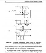
BTW phase-shifted PWM (according to books) is actually something different. See picture.
Phase shifted PWM is meant mainly for ZVS AC-DC / DC-DC converters and cant be used with DC-AC systems (inverters / amplifiers) because the load is fed through a rectifier to convert the PM into PWM. Both gate signals are 50% duty with only phase (alpha)varying.
You will be able to get double frequency PWM by applying XOR (phase detection) between a PM signal and quadrature carrier within a PLL like in the patent cited above.
Cheers. Think different.
Attachments
Last edited:
- Status
- This old topic is closed. If you want to reopen this topic, contact a moderator using the "Report Post" button.
- Home
- Amplifiers
- Class D
- Phase Shift PWM