Is this essential to use XOR gates instead "These tricks" ?
Also why not invert the square with only a single BS170 or a BC547 and a resistor ?
Phase accurate and 81bas dont know the mode control pin of 494. It can work in 0...90 % mode and produce complementary output with the "trick". I built 2 slightly different versions, both worked acceptable. However with the same effort you can build UcD with much better quality.
I've readt in this thread that the one pulse is more long than the other when using this trick 
I like the trick but this confuses me. I am having an oscillo but its not here and I cannot test.
UcD means self-oscillation or its not necessary?
I want two schematics: one with triangle wave generator and one self-oscillating. There are many but i am confused here too because I dont know which one to use.
I like the trick but this confuses me. I am having an oscillo but its not here and I cannot test.
Nice, recommend me a modulator schematicHowever with the same effort you can build UcD with much better quality.
UcD means self-oscillation or its not necessary?
I want two schematics: one with triangle wave generator and one self-oscillating. There are many but i am confused here too because I dont know which one to use.
I've readt in this thread that the one pulse is more long than the other when using this trick
I like the trick but this confuses me. I am having an oscillo but its not here and I cannot test.
The problem is not really the length difference of pulses, but asymmetrical dead time (can go negative in one direction). You have to trim it by carefully chosen R(D)C network, and still it will not be perfect. You definitely need an oscilloscope.
Nice, recommend me a modulator schematic
There are more, for example the one in the "biasing ucd" topic. Search for! I write on mobile, I have limited access and time. Ucd is extremely simple, you can draw sch for yourself.
UcD means self-oscillation
Yes.
or its not necessary?
I want two schematics: one with triangle wave generator and one self-oscillating. There are many but i am confused here too because I dont know which one to use.
I never use sch of anybody elses. I always make my own, only as complex as I can understand. I can recommend this for you. And if you dont know electronics enough, you can experiment in simulator.
This was my stereo, bridgeable amp with 494:
http://www.diyaudio.com/forums/atta...ew-classd-project-starting-0-tl494_amp_tb.jpg
Unfortunately I havent drawn a sch.
Well... it seems like I didn't use any dead time correction in this one. But implemented overcurrent protection.
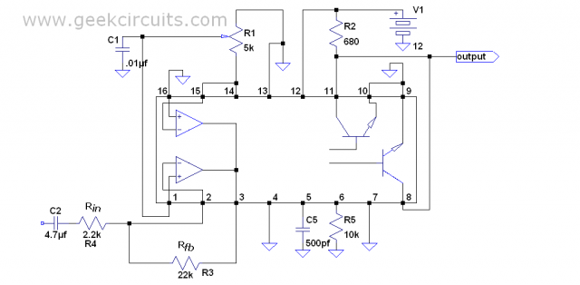
This is one of the simplest implementations of UCD:
http://www.diyaudio.com/forums/atta...op-amp-pwm-design-switching_amp_by_pafi_2.gif
http://www.diyaudio.com/forums/atta...ew-classd-project-starting-0-tl494_amp_tb.jpg
Unfortunately I havent drawn a sch.
Well... it seems like I didn't use any dead time correction in this one. But implemented overcurrent protection.
This is one of the simplest implementations of UCD:
http://www.diyaudio.com/forums/atta...op-amp-pwm-design-switching_amp_by_pafi_2.gif
Last edited:
Thank, pafi.
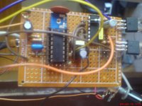
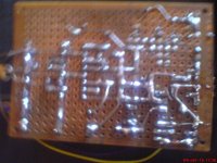
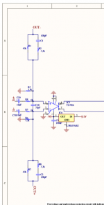
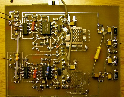
Attached is mine tl494 build which uses the "trick" but its very noisy and its not very loud. Its single supply design and im suppliyng it with 100Vdc.
And this is the biasing scheme im using ->
Thank you for encoarageing me to bias one myself.
Im very interested in self-osc but it seemed complex to me.
Attachments
I didnt remember correctly, this is the thread: http://www.diyaudio.com/forums/class-d/132081-single-supply-bridge-ucd-referencing-signals.html
Against noise (and distortion) usually feedback is useful, but I recommend a preamp instead of high gain of amplifier. Maybe there is problem with the rest of the circuit.
I dont remember the biasing of my design, but probably it used the divided power supply rail.
Against noise (and distortion) usually feedback is useful, but I recommend a preamp instead of high gain of amplifier. Maybe there is problem with the rest of the circuit.
I dont remember the biasing of my design, but probably it used the divided power supply rail.
Last edited:
I've readt this thread, Pafi, but there is no such info like ucd biasing or how ucd works. Maybe this is not the thread.
I've read the info here but cant understand -> Hypex Electronics BV - UcD
I've read the info here but cant understand -> Hypex Electronics BV - UcD
but if you want to understand you need to learn control theory.
What is control theory ?
How to use the attached for half-bridge ?
Just to remove the 2nd feedback ?
What is the maximum modulation of UcD ?
I found a thread here where its used a SG3525 and the thread author claims that modulations is 0 to 98% and also its less noisy than tl494's version.
Attachments
What is control theory ?
Go to Wikipedia!
How to use the attached for half-bridge ?
Just to remove the 2nd feedback ?
I cant display this pdf on mobile.
0 to 100%, however at the ends it behave differently, switching freq drops significantly.What is the maximum modulation of UcD ?
This sound reasonable.I found a thread here where its used a SG3525 and the thread author claims that modulations is 0 to 98% and also its less noisy than tl494's version.
I cant display this pdf on mobile.
Attachments
There are two inputs In+ and In-, how to insert the sound ?
What about IRS900 schematic -> http://dc543.4shared.com/img/KjLhwzo8/s23/139300e6f40/IRS900
??
What about IRS900 schematic -> http://dc543.4shared.com/img/KjLhwzo8/s23/139300e6f40/IRS900
??
- Status
- This old topic is closed. If you want to reopen this topic, contact a moderator using the "Report Post" button.
- Home
- Amplifiers
- Class D
- Doing a class D Amp project using TL494