ok,before build this amp,i've try a UCD topology (with post filter feedback)
i gave up this design because of bad THD,due to the layout,class D amp need SMD component.
sorry,i wrote something false,zobel is 470nF+10 Ohms.
i own a digital scope meter,the SURE kit do not have a zobel on the output.
you can check it easily.
as i said,in this case,component size are very easy for me to exchange,the size do not deteminate the quality of the amp.
i won't take the soldering station for 2 SMD components.
next i will post some THD and IMD measurement.
With all due respect, but this is not a UCD amplifier:
UCD amplifiers I don't particularly fancy because I find them sounding over-controlled, but they DO have excellent distortion specs!!
Please do post some THD and IMD specs! I can compare them with some measurements published here on a Dutch forum, turned out the specs matched the measurements quite precisely!
The size of some components certainly determines the quality of the amp, and the functioning of your HF circuitry!! No wonder the home brewed UCD didn't turn out that great if you don't understand this....

In the TAA4100A datasheet no load operation is not recommended. In any case not without R/C damping network. I would just as a precaution connect a dummyload resistor:
"Tripath also recommends that an RC damper be used after the LC low-pass filter. No-load operation of a TAA4100A amplifier can create significant peaking in the LC filter, which produces strong resonant currents that can overheat the integrated MOSFETs and/or other components. The RC dampens the peaking and prevents problems."
"Tripath also recommends that an RC damper be used after the LC low-pass filter. No-load operation of a TAA4100A amplifier can create significant peaking in the LC filter, which produces strong resonant currents that can overheat the integrated MOSFETs and/or other components. The RC dampens the peaking and prevents problems."
hi V-BRO
you said
With all due respect, but this is not a UCD amplifier:
how do you call a self oscillating,post filter feedback amplifier ?
It's a home brew, not the real thing, many things can go wrong messing up THD performance.
Hot Inductors
I just got my 2 x 100. After initial testing of the amp I went ahead and replaced the input caps and inductors. I used Dayton 2.2uf foil input caps and the Wurth inductors that Scott initially recommended (7443310390). I've been playing for several hours at a low volume and decided to take some temp readings to make sure all is well. The main chip heatsink is 93F, the power caps were 95F, but the inductors read 150F. I confirmed they were really hot by touching the tops of them and immediately had to remove my finger they were so hot. What would make them get so hot? DC offset? I used an IR temp gauge that is pretty accurate. My amp is pretty stock. I am using a 32v 2.5 amp printer power supply for an HP printer. I added 2 1000uf Panasonic FM 50v, and 2 680uf Panasonic FM 50v caps on the power input screws to help with the power dips. Also using an Alps 100k pot for volume control.
I just got my 2 x 100. After initial testing of the amp I went ahead and replaced the input caps and inductors. I used Dayton 2.2uf foil input caps and the Wurth inductors that Scott initially recommended (7443310390). I've been playing for several hours at a low volume and decided to take some temp readings to make sure all is well. The main chip heatsink is 93F, the power caps were 95F, but the inductors read 150F. I confirmed they were really hot by touching the tops of them and immediately had to remove my finger they were so hot. What would make them get so hot? DC offset? I used an IR temp gauge that is pretty accurate. My amp is pretty stock. I am using a 32v 2.5 amp printer power supply for an HP printer. I added 2 1000uf Panasonic FM 50v, and 2 680uf Panasonic FM 50v caps on the power input screws to help with the power dips. Also using an Alps 100k pot for volume control.
The TriPath IS high end audio. Even these modules.
Keep in mind that with high end audio, just as it is with mid range audio. Every time you walk in the room your audio source will sound slightly different, even if its the same exact track.
This is physiological. Many factors account for this:
The material and its source.
Your attitude.
Time of day.
The environment around you.
Where you are standing or sitting.
What the unique volume level might be.
What range your ears are capable of picking up.
As humor, you might I hear it sounds "too controlled", but that might mean the person was probably being controlled.
Any other input on the two different boards? I think the 4*100W looks good. Can I use only 2*100W on that board, will the other 2 channels still draw power if unconnected?
I'd like to avoid the fan version if possible.
To reply to my own question: I just found this thread about the 4*100W, seems to be many problems for now.
http://www.diyaudio.com/forums/clas...ath-board-4-100w-class-d-amplifier-board.html
Still wondering about the different schematics, the 4*100W leads into sda407, then to tc2000 then tk2050, different from 2*100W board which goes directly into tc2000. Any comment on this?
They have a new revision being made to fix the shorting issue, which is on backorder at the moment. 22hrs to go woot. got mine pre ordered with the 14A 24v meanwell... cant wait.. awesome customer service too
4*100 watt @ 4ohm, TK2050 D-class Audio Amplifier Board_Audio Amplifier Boards_Audio Amplifier and other Audio Boards_RF and Audio, Video Equipments_Sure Electronics' Webstore
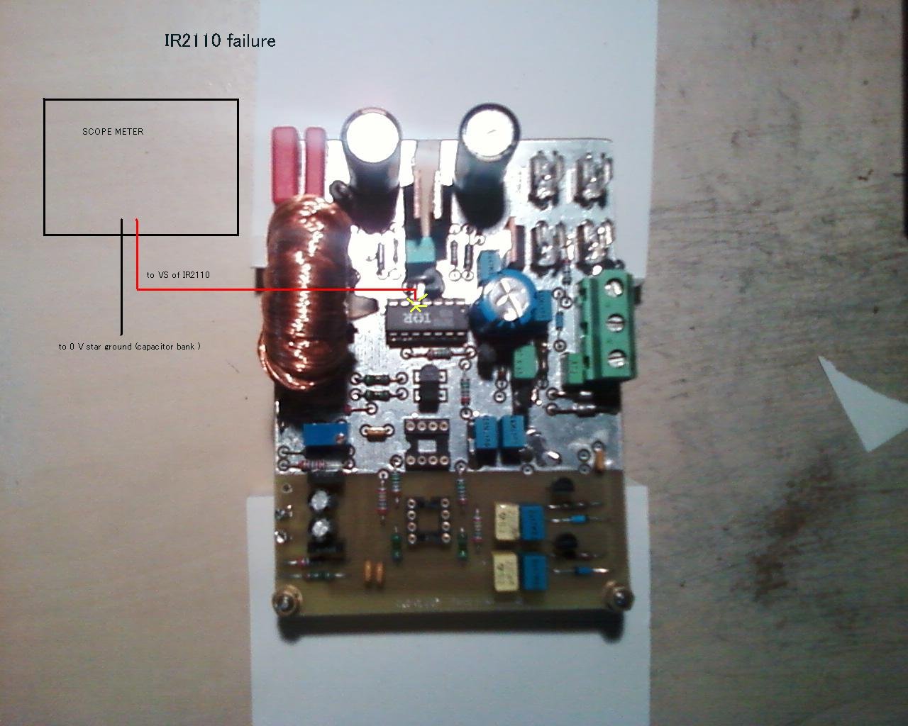
Anyone want to take a stab at why I can fry an egg on my inductors? Would a picture of my board help? They get too hot to touch within 1 minute of powering it on with no inputs connected. I tried to adjust the DC offset using my voltmeter by turning the small metal pots until the meter read 0 millivolts. Not sure I did that right but could not find much info on that.
hi,
you said
I just got my 2 x 100. After initial testing of the amp I went ahead and replaced the input caps and inductors. I used Dayton 2.2uf foil input caps and the Wurth inductors that Scott initially recommended (7443310390)
normal output filter value is 22uH+680 nF
central switching frequency is about 650 kHz
the new coil you are using is only 3.9 uH !!!
in this case,the ripple current in the output coil is far more important
the impedance of the output filter is far lower at 650 Khz.
i think it's a bad idea to lowering coil value,change for a new one with the same value as the stock ( or maybe 18 uH or 15 uH )
the idle current in the TP2050 is quite important with lower value.
Last edited:
3.5uH is cool
I run the Wurth XXL coils at 3.5uH on two different amps and they don't get warm. My air torroids are about 6uH and they don't get warm. You have another problem. Is something shorting the output? You may need to adjust the dc offset with a cheap speaker connected to get it right. Adjust the offset as measured between the speaker terminals. There will always be half supply voltage between each terminal and ground.
Anyone want to take a stab at why I can fry an egg on my inductors? Would a picture of my board help? They get too hot to touch within 1 minute of powering it on with no inputs connected. I tried to adjust the DC offset using my voltmeter by turning the small metal pots until the meter read 0 millivolts. Not sure I did that right but could not find much info on that.
I run the Wurth XXL coils at 3.5uH on two different amps and they don't get warm. My air torroids are about 6uH and they don't get warm. You have another problem. Is something shorting the output? You may need to adjust the dc offset with a cheap speaker connected to get it right. Adjust the offset as measured between the speaker terminals. There will always be half supply voltage between each terminal and ground.
hi,
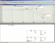
with 3.9 uH,attenuation is 16 db less than a 22uh at 650 kHz
16 db is 6 times more current in the coil, (7 mA -42 ma as the second simulation shows )
36 times more heating even with a low dcr coil...
maybe there 's another trouble.
with 3.9 uH,attenuation is 16 db less than a 22uh at 650 kHz
16 db is 6 times more current in the coil, (7 mA -42 ma as the second simulation shows )
36 times more heating even with a low dcr coil...
maybe there 's another trouble.
Attachments
After reading trough the entire thread (I might have missed a few pages here and there due to fatigue...) and while doing so I've cobbled together a small doc with some images of advised mods and what they should look like.
Posting it here for everyone who's interested. Credits go to all the folks who actually did the research and made the images; thanks for all the great input and ideas
(Sorry for the zip, but Im not allowed to upload the 400kb PDF...)
Posting it here for everyone who's interested. Credits go to all the folks who actually did the research and made the images; thanks for all the great input and ideas
(Sorry for the zip, but Im not allowed to upload the 400kb PDF...)
Attachments
cool coils
My 3.5uH coils are cool. I have been using them for 4 months with no problems. The coils don't dissipate the extra energy. The speaker is the load. Which at 650KHz, the speaker impedance is much, much higher than 8 ohms.hi,
with 3.9 uH,attenuation is 16 db less than a 22uh at 650 kHz
16 db is 6 times more current in the coil, (7 mA -42 ma as the second simulation shows )
36 times more heating even with a low dcr coil...
maybe there 's another trouble.
hi,
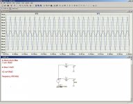
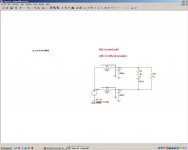
anyway,with or without speaker or zobel,the idle current is flowing through the output LC filter,(4 LC filter for the sure kit )
you can ceck it with a simulator.
this is the output ripple,this voltage is the fundamental of the switching frequency,and the voltage ripple is always existing on the output capacitor.
i believe you that your coils are quite lukewarm.
idle current is so important,better to chose a class ab amplifier.
there is 8 output totem pole (4 per tc2050 ).
the amp is "eating" a lot of current,even in the stock version.
Attachments
Last edited:
Scott, I do not believe I have any shorts on the outputs. The inductors get hot whether there is any speakers connected or not. I will try adjusting the offset with a cheap speaker connected as you suggested. I may have damaged the amp in some way while making the modifications. Thank you Scott for taking a stab at this and especially all the work and testing you have done thus far.
I use this 3.9uh inductor too, and yes it's very hot. I replaced all caps to 0.47 mmk, and Zobel 0.47+15R
Don't know if I broke the board or not, for once I turned it on with one output cable fell off, touched chassis I think. I heard noise from the board, not the speaker, and it sounded like a noisy fan. After put everything back, it seems fine.
Honestly, I think the stocked coils/caps sound very good.
- Status
- This old topic is closed. If you want to reopen this topic, contact a moderator using the "Report Post" button.
- Home
- Amplifiers
- Class D
- Sure Electronics New Tripath Board tc2000+tp2050