Changes and Proposals to Board
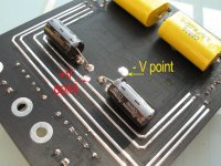
I have now got the 100hrs up on the board so I have taken the opportunity to add some capacitance at the chip, a pair of 470uf/35V ESR caps soldered under the chip, (see pics) and a pair of 1000uf caps in tandem with the std ones on the top of the board. At this point I would say there is some additional tightness to the bass and better attack on notes, not a huge change but worthwhile. Time to let it run for another 15 hrs or so till the coils are added.
I am planning taking power right to the star point between the chips and the earth to the point marked on the pic. I feel the board layout is a bit of a mess and there must be return paths running all over the place in less than ideal arrangements.
I will run a separate power lead to the 5v reg so it is not passing through the board traces, this will come later.
Basically trying one thing at a time to see the results of each step, if any.
Attachments
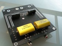
Suntan, interesting brand of capacitor.
It's most probably Chinese and not the common English word.
Regarding the heat, the datasheet says the quiescent current of a TP2050 is 125mA @ 28V which is pretty close to what Scott has measured (300mA for the whole amp). Assuming all that is turned into heat the datasheet numbers would mean 3.5W per TP2050, which is actually quite okay to run without a heatsink. Maybe it does not feel hot because the packaging is not made of metal.
For me, I don't like anything running over 50 degrees, call me over-cautious. So a heatsink meant for motherboard northbridge chipsets later and I'm still complaining.
On second thoughts: 3.5W might be a bit too hot for a package that small. kristleifur, possible to measure the temperature of the TP2050?
Last edited:
PSU and input caps...
Hi,
First I putted 3.2uF Philips MKT caps and 18k resistor. I was not happy with this combination. Yesterday I putted 2.2uF Wima 100v MKS4 caps and 20k resistor. It is much better combination for my system and ears. I am using Monitor Audio RS6i (89db speakers 6Ohm and FE127E diy).
Also simple PSU with two 18000uF caps is better than switching PSU. I am waiting 10uF couls to arive. Then I will continue with mods. Actualy I am very happy with results of just changing input filter.
Great board and sound. I putted in box with volume pot and PSU is in external box. I will probably put biger but passive heatsink. I dont like moving parts in amp :-(
Best regards
On second thoughts: 3.5W might be a bit too hot for a package that small. kristleifur, possible to measure the temperature of the TP2050?
I really should measure. I don't have any kind of usable thermometer :/ Hm ... There are some tech guys in the building, I'll check if they have a meter.
The finger test says around 50-60. When touched, it's not immediately apparent that the chip is HOT, but it does get very uncomfortable after 1-2 seconds.
I dont like moving parts in amp :-(
Well said
*clip*
I feel that the microphonics (if we can call it that) is indeed related to the heat sink, which is spring loaded to the chips, there is in fact very little effort required to wiggle the sink against the springs. I suspect the heat sink chatters against the top of the chip in sympathy with any external vibration and somehow this translates through the system, by means unknown. Pressing down on the heat sink kills the noise totally.
*clip*
I'm surprised that your heatsink is loose. All of mine (earlier, pre-fan boards) have the heatsinks glued to the chips with heat conducting glue. Perhaps you got a defective board that is missing the glue? Even if they have done away with the glue and are using paste instead, the paste should damp out vibrations. Puzzling. Let us know what you discover when you take off the heatsink.
-dr_vega
Hi DV, I took the heatsink off this morning it just clips out, there was paste under the sink, but I added a little more. I tied some copper wire around the nylon clip on the underside of the board and increased the pressure a bit but have not tested it for fan noise/vibration though I have since ran the amp for another 8 hrs. It has 108 hrs on it now.
At this point I would say the amp is very smooth and nicely balanced, there is still some micro grain in the mids which I suspect will disappear once the coils are added. There is certainly no issue with resolution, quite superb in that area.
I have star wired the power supply this evening and will fire it up before I go to bed to check. Currently have one of the Helder 2020 mk 3s burning in, actually it sounded sweet from the first minute!
I won't split off the 5v regulator supply till I have fully tested the current set-up. I expect there may well be some gains to be made there, possibly a pre-regulator down to say 7.5v and remote cap bank could help.
Paste
The third version heatsinks are assembled with the superior heat paste instead of the rubber glue. I am going to measure the temp with the fan disconnected. The new heatsink is actually pretty large.
I'm surprised that your heatsink is loose. All of mine (earlier, pre-fan boards) have the heatsinks glued to the chips with heat conducting glue. Perhaps you got a defective board that is missing the glue? Even if they have done away with the glue and are using paste instead, the paste should damp out vibrations. Puzzling. Let us know what you discover when you take off the heatsink.
-dr_vega
The third version heatsinks are assembled with the superior heat paste instead of the rubber glue. I am going to measure the temp with the fan disconnected. The new heatsink is actually pretty large.
The heat sink never gets even warm with the fan on, I have not tried it with the fan disconnected but I doubt it would get hot unless pushed at higher V. Be interesting to see however just what sort of temps are involved, I suspect Sure may have over-compensated a bit because of the problems with the early boards.
Thanks wwenze for the tip on the paste.
Thanks wwenze for the tip on the paste.
I can confirm that the heatsink fan is audible through the speakers. When I stop the fan with my finger, the buzzing noise goes away. When I release my finger, the pitch of the buzzing rises as the fan spins back up. So the two are linked.
It isn't a big deal, but it adds to the background noise you hear when the amp isn't receiving a signal. Maybe replacing the fan with a bigger heatsink is the solution?
Well, I can report that the fan noise is quite terrible (later blue fans) and is now totally gone. The problem here was running two boards off the one PSU. Disconnecting one amp made the other amp's fan noise silent, reconnecting the fan noise restarted. Now have two PSUs and all fan noise has gone. Also the rating and make of PSUs had nothing to do with this, seems to be some earth loop problem. Hope this helps some of you out.
I have tried everything and I like the Wurth XXL the best.
Hi Scott, not forgotten your recommendation for these, but they are still out of stock over here:
WUERTH ELEKTRONIK|7447709004|CHOKE, SMD, 4.7UH | Farnell United Kingdom
Digi-key belgium still has some: INDUCTOR POWER 4.7UH 9.3A SMD - 7447709004
Digi-key belgium still has some: INDUCTOR POWER 4.7UH 9.3A SMD - 7447709004
Thanks Teamacc, just tried to order 8, but the total came to 0 euros...
On the fan and heat. I tried running the amp sans fan but the heat builds up after about 10 mins, certainly not very hot however in the interests of having a long living amp I feel the fan should be retained or a really large heatsink used.
I have now powered the 5V through a separate cable still from the same battery, interestingly it does seem to make a change to the bass, a bit tighter and fuller, I must say though I have no idea why and did not expect it to do this, overall it just seems a little more dynamic.
I feel the amp would probably benefit from a ground plane below the board, this I feel will lower noise. I have a Helder 2020 mounted on a copper ground plane it is utterly dead quite, no hiss or anything else, I know from experience with other amps and dacs that a close coupled ground plane has benefits so that is what I will do next.
Still no coils added, I want to square everything else away first.
Dr Vega,I took one of my Sure 2*100w amps to a local audiophile meeting Sunday. It is modded with West Cap 2uF paper-in-oil input caps bypassed with .47uF Dayton poly/foil caps. It also has air-core inductors with paper and tin foil shields. Two Panasonic FM 620uF tank caps bolster the power supply. The board is driven by a 36v 3 amp Kodak smps brick from a laser printer.
Three of the people at the meeting have high end tube amps. One of them "hates solid state amps, especially digital amps." The other person is tri-amped with Adcom solid state amps.
After several hours of listening to all kinds of music, all of them agreed that the modified Sure was better than the high end amps they had at home. Even the guy who couldn't stand digital amps conceded that the Sure was as smooth as, and more detailed than, his Rogue Audio tube amp.
This was not a scientific double-blind test. It wasn't even an A/B comparison. It was just some guys who love high quality sound being knocked out by a little amp that cost less than $100 including the power supply and mods.
-dr_vega
Would you mind posting a picture of your air-core inductors with paper and tin foil shields? In fact any pics of your amp would be cool. Also, bypassing the PIOs with the Daytons means you are running them in parallel?
Regards,
Free
Hi there..
i've got a humming noise come in out from my speakers.
Any ideas ?.
I do like that litlle board..
thanks in advance..
Try stopping the fan to see if that's the cause.
hi
Thanks guys.
Im novice just trying to learn a bit from this excellent forum.
Yes i did try stopping fun but there is no difference.
I just got the board and using 12v power supply from my tripath.Still looking for power supply.
And also with modes ,i have that updated version so called.
Should i do some changes ?.
There were lots of photos at the beginning of the forum but most of it don't work anymore.
thanks
- Status
- This old topic is closed. If you want to reopen this topic, contact a moderator using the "Report Post" button.
- Home
- Amplifiers
- Class D
- Sure Electronics New Tripath Board tc2000+tp2050