Hi
Where buy in good price TC2000, and TP2050 in 2 stock ?
Tx
Check http://41hz.com and Gerber Electronics -
(Gerber also have those higher-powered Apogee DDX-2xx0 power stage chips)
Hi Kris! Good to see you here! ")
I can see all you guys are having a lot of fun here doing all the mods! Also, you can learn a lot from this!
So.... has anyone tried the STA517B power stage chip yet? I have built up several amps with this power stage and must say they are incredibly impressive!! There is a massive gain in headroom, yet with the low noise level this chipset is famed for...
I also wanted to mildly warn persons reading this thread that, just like repairing or correcting mistakes on a board, modding a board to perfect it takes much more time and much more soldering skills than building up a board from scratch and do it all right in one draw. So don't kid yourself into thinking this is easier, neither cheaper.
It takes me about two hours to build up a TK2050 amplifier, I see some modded amps in this thread that certainly took a multitude of that time. For example....
I have some spare time while I wait for the new sure board to replace the one I scorched. So I completed the list of mods and things around the board I did. Maybe you find that interesting.
PSU Mean Well 24/145:
- cranked up to almost 30V
- 0.47uF MKS btn GND and COM
Sure board:
- changed PCB traces per audio1st suggestions (diyAudio - View Single Post - Sure Electronics New Tripath Board tc2000+tp2050)
- removed D1,2
- added 0.1uF parallel to C6 from the underside of the board
- exchanged C22&27 for 470pF as per the TC2000 data sheet
- re-wired pins 24 on both TP2050s to 21,22 (Vdd) instead of gnd
- removed tank caps from rails and replaced with 2 x 2 Panasonic FM 1800uF/35V on the rails
- replaced C3 with same type Pana FC
- added 0.1uF/100V MKP4 parallel to C3
- replaced C4 with standard-middle-of-the-road cap 100uF/10V
- replaced R2 with 2 green low-current LEDs, V_F=2.0V
- replaced R3 with 470Ohm
- added diodes 1n4001 btn Vadj/Vout and Vin/Vout
- replaced output filter- replaced R16,30 with 22kOhm metal film
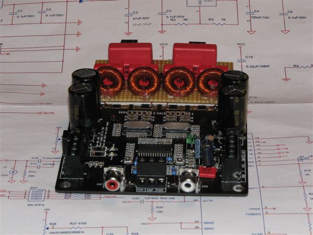
- 12uH self-wound toroids: T68-2 with 46 windings of 0.6mm enameled wire, sets of 2 plain windings followed by 1 clove hitch to double up the wire layer on the inner perimeter of the toroid
- .47 uF/250V MKP4 as common mode capacitors
- .22uF/630V MKP4 (had those in the box) as differential mode capacitor
- .22uF/250V MKP4 as Zobel capacitor
- 10 Ohm/1W Metal Oxide as Zobel resistor
- interrupted traces btn input RCA and screw terminal
- removed R11,27 and replaced with 22kOhm metal film connected btn old solder pad and screw terminal
- removed R4 to open loop over SignalGND, Earth and B1
- added modified Pass B1 buffer (http://www.passdiy.com/pdf/B1 Buffer Preamp.pdf, diyAudio - View Single Post - B1 Buffer Preamp) to input
- 1nF/1000V MKP4 from speaker terminals to chassis
B1 specs
- R1 2.4 Ohm
- C1,2 2 x 3 x 3800uF/35V Panasonic FC
- C3 1uF MKP-10
- Cx00: 1uF MKP-10
- Cx01: 2.2uF MKP-10, directly linked to input resistor of sure board
- Rx05,x05: dropped
- 50k Vishay conductive plastic, log taper
- added 1N5401 to input of positive rail, bypassed by a 1k resistor for a controlled discharge of the caps (otherwise the sure amp makes an ugly noise when going down)
Soft Start/ Mute On Off Circuit
- 24V/0.4W relay 8A 2CO contacts (tyco RT424024)
- 2 white LEDs (~6V drop) in line with coil
- 47 Ohm/ 5W resistor to fill the tank caps up to operating voltage for the relay
- 1N4148 parallel to relay coil
- 0.39 Ohm/5W resistor to filter the power supply and to sense the current
- TL081 as comparator (TL081 can work in high-side applications)
- 2 x 10k voltage divider to drive a
- BS170 that mutes the amp when power is switched off and the tank caps unload via the SMPS and the current sensing resistor
- 100uF btn MUTE and GND to keep the amp mute a little longer
- 3 x 3300uF/35V Yageo SY tank caps
- 1800uF/35V Panasonic FM next to output (close to amp power input)
piccie of the board w/ toroids and schematic of the "mute on off" circuit attached
Forgive me if this has been asked and answered, but has anyone directly compared the Sure amp modified or unmodified with the Virtue Audio 1, 2. or 1.2?
I've heard TA 2020's in different configurations and the sound can be noticeably different though the basic character doesn't change a lot. I'm assuming the same would be true of the Sure and the Virtue Audio, but don't really know.
I've heard TA 2020's in different configurations and the sound can be noticeably different though the basic character doesn't change a lot. I'm assuming the same would be true of the Sure and the Virtue Audio, but don't really know.
It is true that the chipset is responsible for the main character of the sound, but what comes on top with a poorer design is noise, hiss and more distortion. The degree in which this happens can vary quite a bit from design to design. This has nothing to do with the use of exotic components and such, but just by proper understanding of the purpose of the components and finding the most adecquate part for the job.
Hi Joe, no I have no time at all to make my own PCB for this, I am working on totally different designs, like SMPS and such...
I have used 41hz AMP4 and AMP11 with this chip and it is a tremendous gain in power!
Here's more about the AMP4-HV:
AMP4-HV, it's alive!!
And more about the AMP11-HV:
AMP11-HV monoblock pictures!!
I have used 41hz AMP4 and AMP11 with this chip and it is a tremendous gain in power!
Here's more about the AMP4-HV:
AMP4-HV, it's alive!!
And more about the AMP11-HV:
AMP11-HV monoblock pictures!!
Last edited:
Fill me in... are you saying this would be a good part to modify the sure 2*100 board with? What benefits would it carry? (I assume higher output due to higher voltage/amperage....)
10 more volts
The Sure amp with it's stock TK2050 can be pushed up to 40v just by changing resistors R13, 17, 25, 31 to 19K. To go to 50v with the 517 would require the same resistors to be changed to 24K and also taking the 5v regulator off of the board to use two stages. Any higher than 50v would need all of the 50v electrolytics replaced as well and would need special attention to the heatsink to keep it from burning up. You might also want bigger coils than the 10amp Wurths I have been using such as the SER2900. It starts to get into a lot of work to change those tiny chips and mess with the regulator to go over 40v. Maybe if I blow a 2050 I might try a 517 at 40v to hear how it compares.
The Sure amp with it's stock TK2050 can be pushed up to 40v just by changing resistors R13, 17, 25, 31 to 19K. To go to 50v with the 517 would require the same resistors to be changed to 24K and also taking the 5v regulator off of the board to use two stages. Any higher than 50v would need all of the 50v electrolytics replaced as well and would need special attention to the heatsink to keep it from burning up. You might also want bigger coils than the 10amp Wurths I have been using such as the SER2900. It starts to get into a lot of work to change those tiny chips and mess with the regulator to go over 40v. Maybe if I blow a 2050 I might try a 517 at 40v to hear how it compares.
Straight off (on the same voltage) this chip would make the amp 2ohm stable, but by changing a bunch more components you could indeed run the whole amp on max 52Vdc. With the mono mode amperage of 12A you can do the math on how much more powerful it'll become! Roughly three to four times as powerful!!
Of course, If building a new 41Hz from the ground up you might as well use the 517.
Even if you don't, ever heard of Chipquik?
YouTube - Using ChipQuik to Desolder Surface Mount Components
Hi Kris! Good to see you here!
I can see all you guys are having a lot of fun here doing all the mods! Also, you can learn a lot from this!
So.... has anyone tried the STA517B power stage chip yet? I have built up several amps with this power stage and must say they are incredibly impressive!! There is a massive gain in headroom, yet with the low noise level this chipset is famed for...
I also wanted to mildly warn persons reading this thread that, just like repairing or correcting mistakes on a board, modding a board to perfect it takes much more time and much more soldering skills than building up a board from scratch and do it all right in one draw. So don't kid yourself into thinking this is easier, neither cheaper.
It takes me about two hours to build up a TK2050 amplifier, I see some modded amps in this thread that certainly took a multitude of that time. For example....
I was having a lot of fun doing the mods. And I learnt a lot. And I didn't fancy mounting 36-pin SMD chips, so I took the board and modded...
Hi Guys,
My first post ! Ok, done the most basic mods for the TA2050: Input caps/ removed bass roll off and peak level limeter.
Think next must be the power supply. Here can go two ways, battery or not.
But First need to establish voltage - 24v be ok ? I can go for a 36v one, but would be scared of frying it....
Would this do ?:
24V 10A DC Universal Regulated Switching Power Supply on eBay (end time 14-Mar-10 13:32:55 GMT)
Take it that 10amps would be enough ? As far as batteries / chargers are concerned I know nothing about and would not know what to buy. But are batteries that much better sounding ?
Many thanks in advance !
Noise!
Lots of noise problems with this baby...
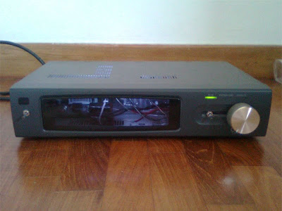
Firstly, the Meanwell 24V PSU having some stray EMI is an understatement. Due to bad layout as seen in the photo I had long lengths of wires alongside the PSU, and woo was it noisy.
Took me up to 3 layers of aluminium foil to tame it, two wasn't enough, I could still hear noise over my computer at max volume.
Noise source number 2 - the fan, forget the subtle improvement of SQ with that fan removed, it is possible to hear the fan spinning through the speakers. I can confirm it's the fan because when it is stopped with my finger, so did the buzz.
The fan, it's more a curse then a gift!
Lots of noise problems with this baby...
Firstly, the Meanwell 24V PSU having some stray EMI is an understatement. Due to bad layout as seen in the photo I had long lengths of wires alongside the PSU, and woo was it noisy.
Took me up to 3 layers of aluminium foil to tame it, two wasn't enough, I could still hear noise over my computer at max volume.
An externally hosted image should be here but it was not working when we last tested it.
Noise source number 2 - the fan, forget the subtle improvement of SQ with that fan removed, it is possible to hear the fan spinning through the speakers. I can confirm it's the fan because when it is stopped with my finger, so did the buzz.
The fan, it's more a curse then a gift!
Lots of noise problems with this baby...
The fan, it's more a curse then a gift!
If I were you I would install the power supply on the left side and the amp on the right this way your mains (120Vac or 230Vac) remains on the left side where your mains entered the enclosure and the amp is close to the amp instead of being the power supply near your pot.
Eric
If I were you I would install the power supply on the left side and the amp on the right this way your mains (120Vac or 230Vac) remains on the left side where your mains entered the enclosure and the amp is close to the amp instead of being the power supply near your pot.
Eric
Yea I know, that's what I'd have done if possible, but problem is this isn't a project case but a chassis of some Japanese cable TV decoder, and the left side isn't flat enough (there were some wierd pimples) to mount the PSU with proper contact of the heatsink to the case.
As for the volume knob, I had to put it at the right for aesthetic reasons ^^ :
Well, at least now the fan is the bigger problem. Lets see how hot this run without.
Last edited:
- Status
- This old topic is closed. If you want to reopen this topic, contact a moderator using the "Report Post" button.
- Home
- Amplifiers
- Class D
- Sure Electronics New Tripath Board tc2000+tp2050