I have an amp that has a heavy board (car audio class D) and between that and vibration it causes fet legs to break with a cascading effect. There is no way to better secure the board but is there a way to remote mount the fets to the sink using a copper braid between the PCB and the legs to isolate vibration/movement ? Has anyone done this and if so could you paste up some pics? I know thinks like this exist especially if you look at alternator/electrical motor brushes it is done this way. Only thing I need to make sure is if the braid can handle the current. I was looking at copper desoldering braid. Any and all input welcome... ")
In general, it is not adviseable to add lengths of wire to switching mosfets. Especially in high frequency the added wire inductance can cause you nasty problems such as ringing, added dissipation etc.
However, I have seen it before in DC/DC converter applications switching at 130kHz.
1. Keep the wires as short as possible. Generally no more than 3 - 4 cm.
2. Keep Gate, Drain and Source wires close to one another to minimise loop inductance. Do not twist the wires tightly however... This will only add inductance.
Good luck!
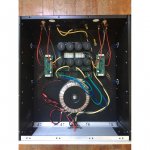
such as this... are there any sonic disadvantages?
Yes, that's very bad. At the high switching frequencies that's an oscillating circuit and it's killing the dead time adjustment and that means the transistors will likely fry. Even worse: You can expect DC at the output when that happens and since you've got no protection on the amp, that will fry your speakers too.
And there's actually no reason to have them that long, just move the boards to the heatsinks/enclosure wall. Much better: Split the capacitor board and keep the wires short between the caps, enclosure and FETs.
On the contrary twisting the leads together will minimize inductance - there is no net current flowing in the bundle so the twist doesn't add any inductance, but will keep loop area low (and reduce noise pickup and EMI).2. Keep Gate, Drain and Source wires close to one another to minimise loop inductance. Do not twist the wires tightly however... This will only add inductance.
There's an issue, which is the increased capacitive coupling between gate and drain which is bad news.
So it turns out the best way to wire is two twisted pairs, one for drain/source, one for gate/source.
Some large power MOSFETs come with 4 terminal screws, gate, source, drain, source.
2. Keep Gate, Drain and Source wires close to one another to minimise loop inductance. Do not twist the wires tightly howeve!
I dislike the idea of have the drain wire close to the gate one. This increases Miller capacitance. I suggest keep close gate and source wires together, but drain far from them.
- Home
- Amplifiers
- Class D
- Remote mounting fets