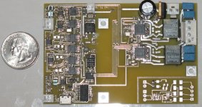
i'm pretty new to class-d, so i'm more familiar with tube designs. in that spirit, the analog devices series of integrated class-d amplifiers has caught my attention. i've designed a board based on figures 44, 45, and 49 in the device datasheet:
http://files.geekysuavo.org/classd/adau1592.pdf
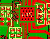
my board design is available in open-source PCB format, Gerber format, and PNG format at http://files.geekysuavo.org/classd/ . the bom.html file lists the specific digikey part numbers of the components i chose.
if anybody is interested, it's up for grabs. more than anything, i'd love scrutiny of the design, as i'm still new to this amplifier topology.
thanks,
~ brad.
I'm curious if anyone's aware of a class D chip with fidelity comparable to the ADAU1592 but available in a more DIY friendly package. I'm looking for class D solutions with peak outputs in the 1W to 10W range with performance equivalent or superior to the LM3886or LME49600. The ADAU1592 is the only chip I can find which meets these criteria. But its TQFP version is discontinued (and would be a hassle to solder) and the LFCSP is hard enough to work with its easier to put heatsinks on a class B part.
Failing that, are there any soldering services which would be able to stick a ADAU1592 at reasonable cost?
Failing that, are there any soldering services which would be able to stick a ADAU1592 at reasonable cost?
I'm curious if anyone's aware of a class D chip with fidelity comparable to the ADAU1592 but available in a more DIY friendly package.
When you say "fidelity comparable to the ADAU1592", is this something you have actually heard, or are you just going by the numbers?
Do you think you could tell the difference in a blind test between 0.005% THD+N and 0.03% THD+N?
If not, the new TAS5615 or TAS5630 could be the answer. They have 15dB greater PSRR than the ADAU1592 (80dB vs 65dB), which to me is more important than the difference in THD. They have plenty of power to boot, which would address vincent's comment above.
Last edited:
No, but I would like total distortion (and certain other artifacts) to be 50dB down for the overall system at output powers in the range of 100uW to 1mW. So reasonable confidence a chipamp would be around or below 0.1% THD+N at 1mW is desirable to allow some headroom for IMD and such. I appreciate the suggestion, but parts such as the TAS5615 and TAS5630 unfortunately aren't a good fit for this requirement (there's a reason I mentioned the LME49600 and peak outputs of 1WDo you think you could tell the difference in a blind test between 0.005% THD+N and 0.03% THD+N?
Since the THD+N scaling of class D amplifiers at low power isn't as good as class B I'd actually prefer a less powerful part than the ADAU1592, but lower wattage parts all seem to target the low-fi market of 1 to 10% THD+N. Whereas I'm trying to see just how much heat I can shave off the thermals of a low power hi-fi solution.
I'm curious if anyone's aware of a class D chip with fidelity comparable to the ADAU1592 but available in a more DIY friendly package.
The ADAU1592 isn't that hard to solder. Most of the pins are doubled or tripled, and the single pins really aren't that hard to solder. Just use lots of solder and then wick off the excess.
It's a very nice little amp. Dead quiet and low distortion.

Yeah, not too bad if you have TQFP old stock as used on the board above. If you don't, you're stuck with an LCSFP as the TQFP's discontinued. That's rather harder.
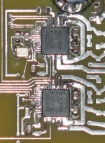
The two ADAU1592 chips are LFCSP_VQ--they are on the right side of the board. I repeat: not that hard! All I have is a 30-year old Weller iron with a fine tip.
The stuff on the left side is an active crossover with TSSOP packages.
Look ma, no legs...

Last edited:
I'd correctly located the chips, just got confused between traces and pins amid the lack of pixels.How'd you handle the bottom pad? Hot plate?
Vias. It's just one of those ExpressPCB prototype boards, and there is a limit on drill size and hole closeness, but even so you can pack a lot of vias under the chip. I solder from the back side with a 700 degree tip to fill the vias. Not sure how much solder bonds to the chip thermal pad, but the board gets somewhat warm, so the heat transfer seems good enough.

Interesting. How much output power have you tested with? Any measurements on how warm the chip gets? I have an itty bitty low dissipation biamp project on the back burner that the ADAU1592 is a good fit for (differential input, LR6 crossover, two channel out in three chips  ).
).
Interesting. How much output power have you tested with? Any measurements on how warm the chip gets? I have an itty bitty low dissipation biamp project on the back burner that the ADAU1592 is a good fit for (differential input, LR6 crossover, two channel out in three chips).
I don't know, and I probably won't do anything with this circuit for a while. Stupidly enough, the only circuitry I really needed right now on that board was the small section in the lower right corner. But I didn't want to waste an entire board, so I put on some stuff that I was interested in evaluating.
A while back I had made some amps with the AD1994 and I liked them...and was disappointed that AD discontinued them. So I thought what the heck...I'll give the ADAU1592/ADAU1590 a try. The other circuitry is a rather neat active crossover design--see this thread: Any interest in small active crossover board? - Techtalk at Parts-Express.com
I probably won't spend much more time with the ADAU1590 for a while--got too many other projects ahead of it. I think it sounds good and it doesn't get more than warm even at moderate listening levels. It's very quiet--no background hiss at all. The protection circuit seems to work well: short out the output and you get a nice spark, but just reset the chip and all is good again.
I have tried Hypex UcD400 / Connex Philips TDA8920 / SURE Tripath TA2024 / SURE Tripath TK2050 TP2050. I love the fact that these boards are so small and cheap so I can test many. For the last three boards I named I am using the same transformer just configured differently. For the last two boards I am using the same rectifier and cap (fot the TA2024 a 12v reg is needed to drop down the 24v to 12v).
I should post a formal review. I am running these on a Tekton Design Fostex 6” FE166En (94db) speakers. I am feeding it with the Twisted Pear Audio - USB DAC/Receiver module.
The Hypex doesn’t sound good on full range speakers. I think it’s the post filter feedback. It is the most costly boar. Fortunately, all the other boards sound pretty good with full range speakers.
I sit pretty close to the speakers and noise is the biggest problem, my tube amps are much quieter. The TDA8920 is the quietest. That is not even using the balanced input (which is a nice high end feature). The Tripath’s have more noise but they also have a slightly clearer high end. So there is no clear winner, only trade-offs.
I am hoping to try the ADAU1592 at some point in the future. The Philips is a classic triangle comparator type modulator, the Tripath is a 2nd order delta-sigma modulator and the Analog Devices is a 5th order delta-sigma modulator so in theory the noise should be less at lower frequencies. If it had the high end clarity of the Tripath and the low noise of the Philips TDA8920 it could be a real winner, I don’t know if this is the case though, that’s why I want to try.
The only built up board I know of is the Analog Device evaluation board which is costly at $244.63. There is also no supplier having it in stock. I am inquiring to Arrow about getting one of these. I really don’t want to build a board because of the effort involved, before I can compare it to the other boards. Also for DIY efforts the package they selected really sucks. A SOIC package with a heat-pad would be nice (hint hint, if there are any AD Engineers out there). Unfortunately unlike the Philips TDA8920 the Analog Device ADAU1592 does not come with balanced inputs
 . The Analog Device does give a thermal warning
 which is nice, but it requires an external clock which is another hassle
  the Philips clock is internal, but it’s lower speed.
I should post a formal review. I am running these on a Tekton Design Fostex 6” FE166En (94db) speakers. I am feeding it with the Twisted Pear Audio - USB DAC/Receiver module.
The Hypex doesn’t sound good on full range speakers. I think it’s the post filter feedback. It is the most costly boar. Fortunately, all the other boards sound pretty good with full range speakers.
I sit pretty close to the speakers and noise is the biggest problem, my tube amps are much quieter. The TDA8920 is the quietest. That is not even using the balanced input (which is a nice high end feature). The Tripath’s have more noise but they also have a slightly clearer high end. So there is no clear winner, only trade-offs.
I am hoping to try the ADAU1592 at some point in the future. The Philips is a classic triangle comparator type modulator, the Tripath is a 2nd order delta-sigma modulator and the Analog Devices is a 5th order delta-sigma modulator so in theory the noise should be less at lower frequencies. If it had the high end clarity of the Tripath and the low noise of the Philips TDA8920 it could be a real winner, I don’t know if this is the case though, that’s why I want to try.
The only built up board I know of is the Analog Device evaluation board which is costly at $244.63. There is also no supplier having it in stock. I am inquiring to Arrow about getting one of these. I really don’t want to build a board because of the effort involved, before I can compare it to the other boards. Also for DIY efforts the package they selected really sucks. A SOIC package with a heat-pad would be nice
I wouldn't mind on chip balanced inputs either, but I doubt Analog would go for it as it'd require a more extensive analog front end and a negative supply rail (or on die AC coupling caps). It's really not a big deal to throw an LME49720 in front of the ADAU1592. One would probably want to do that anyway since with a 15V PVDD the part swings cleanly to about 12.5V so the 1592's minimum gain of 19dB is overkill and it's desirable to front it with an attenuating stage. Personally I'm more annoyed by the apparent requirement for AC coupling; the suggested 2.2uF is too big for C0G and I'm somewhat reluctant to use X7R, though a 50V 1206 should be decently linear. The quick solution is just to throw Elna RFSes in there and get on with life. But I am not used to these big leaded parts. 
I have a bit of extra area in a run going out soon for another project so I'm going to try to piggyback in a 1592 board if I can get one together in time. Any thoughts on the supplies? As the 1592 has only 67dB PSRR I want PVDD to be pretty clean but I don't have a super regulator design handy and don't have time to put one together. At the moment I'm thinking an LM350 with the bypassing recommended in the datasheet. AVDD and DVDD are more straightforward---LM2936 is the best option I've found so far for tapping directly off the unregulated rails (20V nominal, can get to 35V with light load and the mains running high) but a 78L12 followed by a pair of 78L33s (one for AVDD, one for DVDD) is cheaper and works better. So much for elegance.
I have a bit of extra area in a run going out soon for another project so I'm going to try to piggyback in a 1592 board if I can get one together in time. Any thoughts on the supplies? As the 1592 has only 67dB PSRR I want PVDD to be pretty clean but I don't have a super regulator design handy and don't have time to put one together. At the moment I'm thinking an LM350 with the bypassing recommended in the datasheet. AVDD and DVDD are more straightforward---LM2936 is the best option I've found so far for tapping directly off the unregulated rails (20V nominal, can get to 35V with light load and the mains running high) but a 78L12 followed by a pair of 78L33s (one for AVDD, one for DVDD) is cheaper and works better. So much for elegance.
Nichicon KZ is another option. Digikey has 22 uF. That should be adequate.
Otherwise, Wima MKP4 or Panasonic ECG "orange drops" seem to be the best options. I find it rather ridiculous to use a cap of that physical size, though. Even with on-board regulators, those input caps will occupy the largest part of the circuit.
~Tom
Otherwise, Wima MKP4 or Panasonic ECG "orange drops" seem to be the best options. I find it rather ridiculous to use a cap of that physical size, though. Even with on-board regulators, those input caps will occupy the largest part of the circuit.
~Tom
Any of the audio grade films or 'lytics would be fine---I just happen to default to Elna RFS. In most cases the f_low increase from tweaking Analog's suggested input network to use 1uF 16V 1210 PPS parts should be viable---page 19 of the 1592 datasheet suggests the input impedance is fairly well controlled.
An alternative option I like better is to avoid DC blocking by referencing the differential to single ended conversion fronting the 1592 to the 1592's Vref pin (same approach works for reference shifting with unbalanced inputs). Datasheet doesn't seem to mention anything one way or the other about doing this but, since the 1592's input and output end up sharing a quiet reference, noise rejection might well turn out better than a more traditional ground star arrangement. In this arrangement I'd be tempted to take Cref to zero if it weren't for the datasheet mentioning the modulator uses Vref and Cref acts as an AVdd filter; instead 10uF 25V X7R 1210 is probably the sweet spot for a compact Cref. (I'd be surprised if the noise from something like a 49710 or 49990 is significant compared to what the 1592 puts into Cref.)
An alternative option I like better is to avoid DC blocking by referencing the differential to single ended conversion fronting the 1592 to the 1592's Vref pin (same approach works for reference shifting with unbalanced inputs). Datasheet doesn't seem to mention anything one way or the other about doing this but, since the 1592's input and output end up sharing a quiet reference, noise rejection might well turn out better than a more traditional ground star arrangement. In this arrangement I'd be tempted to take Cref to zero if it weren't for the datasheet mentioning the modulator uses Vref and Cref acts as an AVdd filter; instead 10uF 25V X7R 1210 is probably the sweet spot for a compact Cref. (I'd be surprised if the noise from something like a 49710 or 49990 is significant compared to what the 1592 puts into Cref.)
An alternative option I like better is to avoid DC blocking by referencing the differential to single ended conversion fronting the 1592 to the 1592's Vref pin (same approach works for reference shifting with unbalanced inputs).
I like that. And I happen to know just the circuit that'll do that. A transformer... Like the Jensen JT-11P1. But at $65 and umpteen times the volume of the entire class D amp it does seem like putting 10 lbs of sh*t in a 5 lb bag...
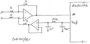
One could also use a differential amp. Connect Rg to Vref rather than GND and you get Vout = Vin(Rf/R1)+Vref (for Rg = Rf; R1 = R2). I'd be tempted to filter and buffer Vref as its output impedance isn't spec'ed anywhere. Aside from 20 kOhm, typ neither is the input impedance by the way. With process variation and such, it's probably +/-10 % - so "tight enough".
In this arrangement I'd be tempted to take Cref to zero if it weren't for the datasheet mentioning the modulator uses Vref and Cref acts as an AVdd filter;
Yeah, with that happy house of switching and 5th order MASH (or whatever spread spectrum modulator they use), I'd want that Vref to be quiet. 100 uF tantalum plus 1 uF MLCC, maybe with an additional 10 nF C0G or X5R in parallel would seem reasonable. Or MLCC instead of the tantalum. It's only sitting at AVdd/2 = 1.65 V (typ). One could get away with 6 V caps, though with the voltage coefficient of MLCC's using a higher voltage type is probably not a bad idea.
(I'd be surprised if the noise from something like a 49710 or 49990 is significant compared to what the 1592 puts into Cref.)
Me too. One could also filter it... Stare at attached.
~Tom
Attachments
Random thought of the day (or actually yesterday): I want the amp to operate autonomously, i.e. without micro controller (or user) intervention in the event of a failure. The ADAU1592 provides a "warning" and an "error" output. However, the datasheet warns about connecting the error (/ERR) directly to the /MUTE input as the amp will power cycle and burn itself up in the event of a short circuit on the output.
As both the /OTW and /ERR outputs are open drain, why not just "OR" them and use the result to drive /MUTE? With the open drain outputs, all one would have to do is to connect /OTW, /ERR, and /MUTE together with a pull-up to DVDD.
That way the amp would shut off in the event of a failure (clock loss, PVDD, DVDD loss, short circuit) but never reach a temperature higher than the "warning" threshold.
Do any of you see issues with this approach?
~Tom
- Status
- This old topic is closed. If you want to reopen this topic, contact a moderator using the "Report Post" button.
- Home
- Amplifiers
- Class D
- analog devices adau1592
