Hi All,
I recently showed my Philips patented or Bruno Putzey's based 6Ch Car amplifier on Eva's thread( http://www.diyaudio.com/forums/showthread.php?threadid=111566&perpage=25&pagenumber=2) Post 29.
At first I would like to say I will not give a shematic or layout this is a known amplifier and one can reach the shematic with a bit searching.
Today I get some measurements.
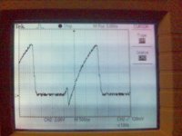
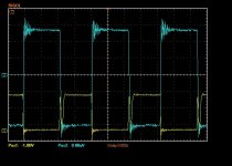
Here is the low side mosfet G-S photo. As Eva said before she is right and my L mosfet gate signal is not good as I expect. These "IRFP250N or 150N" are heavy mosfet to drive with this discerete driver. But I think it is possible to improve this signal better then now and I need your advice.
My amplifier runs cool. It is now supplied with un regulated (no FB) 12V to 75V smps(~+/- 37V). It gives 75W/Ch RMS on to 5ohms resistive load before the output sine wave saturated. Ah....input signal 2V rms un balanced 1KHz. I had a look to supply lines and saw some 200mV pk to pk ripple. But the output signall is very clean squarewave.
All comments are welcome.
Regards
Ps: The scope is Tektronix 60MHz 1G/s. Signal source Wavetec 1MHz signal generator. Output residual signal on idle 500mV pk to pk 424kHz.
I recently showed my Philips patented or Bruno Putzey's based 6Ch Car amplifier on Eva's thread( http://www.diyaudio.com/forums/showthread.php?threadid=111566&perpage=25&pagenumber=2) Post 29.
At first I would like to say I will not give a shematic or layout this is a known amplifier and one can reach the shematic with a bit searching.
Today I get some measurements.
Here is the low side mosfet G-S photo. As Eva said before she is right and my L mosfet gate signal is not good as I expect. These "IRFP250N or 150N" are heavy mosfet to drive with this discerete driver. But I think it is possible to improve this signal better then now and I need your advice.
My amplifier runs cool. It is now supplied with un regulated (no FB) 12V to 75V smps(~+/- 37V). It gives 75W/Ch RMS on to 5ohms resistive load before the output sine wave saturated. Ah....input signal 2V rms un balanced 1KHz. I had a look to supply lines and saw some 200mV pk to pk ripple. But the output signall is very clean squarewave.
All comments are welcome.
Regards
Ps: The scope is Tektronix 60MHz 1G/s. Signal source Wavetec 1MHz signal generator. Output residual signal on idle 500mV pk to pk 424kHz.
Attachments
Ouch, the cycle ends and the gate hasn't had enough time to charge 
But if you really want to check wether waveforms are good or not, try connecting a big 5 to 10 ohm dummy load between the output and each supply rail. You have to connect it after the circuit has started oscillating. This is a basic test setup for body diode hard swiching. Such a test is required because things change a lot when output current increases and the amplifier is no longer working in resonant mode... Then all layout resonances arise...
But if you really want to check wether waveforms are good or not, try connecting a big 5 to 10 ohm dummy load between the output and each supply rail. You have to connect it after the circuit has started oscillating. This is a basic test setup for body diode hard swiching. Such a test is required because things change a lot when output current increases and the amplifier is no longer working in resonant mode... Then all layout resonances arise...
Eva said:Ouch, the cycle ends and the gate hasn't had enough time to charge
But if you really want to check wether waveforms are good or not, try connecting a big 5 to 10 ohm dummy load between the output and each supply rail. You have to connect it after the circuit has started oscillating. This is a basic test setup for body diode hard swiching. Such a test is required because things change a lot when output current increases and the amplifier is no longer working in resonant mode... Then all layout resonances arise...
I see what you mean and will try but a bit later. As you know I can not leave much far from home now. However all my test was done with an dummy 5R 200W resistor from audio autput to GND. I think only cahnging the output mosfets to TO220 IRF540Z will put these out. But I would not want to do this. I will try Zetex FZT619 or NXP PBSS5240T for fast shut of Mosfets. I am using only BC807-40 with a 470R B-C resistor( in normal application it is 1K with PBSS5140T). Is not this 470R a bit big load for opening transistor? Which is also a BC807-40 with 390R B-E resistor.
Regards
luka said:Hi Whortless
I just love this multi channel amp, gate signals could be better... hope that you will look into this... Now for my request: Could you send me some Hi-Res pic of this amp, bottom and other side, I just love how you did all channel on one board + used SMDs.
Phostos goes to your e-mail.
Regards
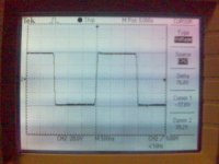
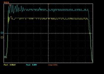
Ah Sorry I have forgotten to say all the amplifiers can be sync to a good 424Khz sw frequency( self osc 325 to 375kHz).
Here is the out put waveform.
And so sorry for low resolution they are from my cellphone. I have forgotten to take my camera while going to the audio lab.
Attachments
Improvements, Help needed!
Dear All,
I made the above amplifier ~1 year ago and could not find some time to correct its gate wave froms. I know that there are several amplifiers and many similar applications submitted here. But I was unable to follow the discussions because of very hard works on chemistry.
Anyway I have bought an osciloscope( Rigol DS1022 CD) recently and start to work on this amplifier.
I made some improvements to achieve the correct on/off of output mosfets (IRFP150N). I know the old IRFP150N is a very heavy mosfet to achieve good switching. First I replaced the Mosfet driver to BC807-100 (Q8 and Q10) and the shut off transistor to PBSST5240T (Q9&11)on the enclosed shematic. And I obtained the enclosed mosfet gate wave forms.
Attachments
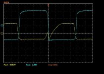
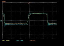
But, I could not find a solution to fast shut of the high side mosfet.
The photo below shows the L (yellow)and H mosfet gate waveforms. I could not remove the peak before the real open signal of L gate. I tried nearly everyting. Also replaced the mosfets into IRF540N.
All comments are welcome.
The photo below shows the L (yellow)and H mosfet gate waveforms. I could not remove the peak before the real open signal of L gate. I tried nearly everyting. Also replaced the mosfets into IRF540N.
All comments are welcome.
Attachments
- Status
- This old topic is closed. If you want to reopen this topic, contact a moderator using the "Report Post" button.
- Home
- Amplifiers
- Class D
- Philips Patented UCD "My 6Ch Car Amp"