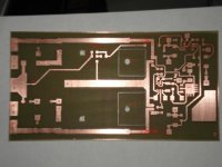
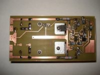
Here is picture of my PCB and some components markings on.
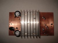
PCB is double sided.PArts are on top side and GND is all bottom side.Heatsink will me mounted on bottom side of PCB.I will cut off PCb where IRF540 are and mount them on heatsink.
I still need answers on my previous question.
Thanks
PCB is double sided.PArts are on top side and GND is all bottom side.Heatsink will me mounted on bottom side of PCB.I will cut off PCb where IRF540 are and mount them on heatsink.
I still need answers on my previous question.
Thanks
Attachments
Judging by the questions about elementary electronics that you make, you don't seem to be ready at all for such a project (and there is already too much low-quality class D out there giving us a bad name  )
)
The theoretical maximum RMS power output is V^2/(2*R) where V is peak output voltage, that you can assume to be rail voltage (40V for your case). Do the math. For class D you have to ensure that both the MOSFETs and the output inductor can handle the required peak current for the rated impedance (at least 10A for 40V on 4 ohms). Inductor must not saturate.
Concerning the gate driver, have you looked at the datasheet? In top right side of the first page you will find a square filled with big numbers and letters in it. Those numbers and letters are YELLING something like "don't even try this IC for class D", and you should learn to interpret them before continuing the project.
)The theoretical maximum RMS power output is V^2/(2*R) where V is peak output voltage, that you can assume to be rail voltage (40V for your case). Do the math. For class D you have to ensure that both the MOSFETs and the output inductor can handle the required peak current for the rated impedance (at least 10A for 40V on 4 ohms). Inductor must not saturate.
Concerning the gate driver, have you looked at the datasheet? In top right side of the first page you will find a square filled with big numbers and letters in it. Those numbers and letters are YELLING something like "don't even try this IC for class D", and you should learn to interpret them before continuing the project.

Ok you can do an amplifier but, the problem will be the quality. If I were you would use 2110,2113 perhaps 2011. The IC you would like to use has internal ~500ns deadtime which will cause crossover distorsion like an unproper biased classAB amplifier. Also the IC has long ton/off speeds and has low drive capability. I think an expert "Eva" can give more explanation.
Any way I do not know if are they pin compitable but , try HIP2100/2111(ISL2111/2110) or LM5104/5105 . You should consider your driver selection.
Good luck!
Any way I do not know if are they pin compitable but , try HIP2100/2111(ISL2111/2110) or LM5104/5105 . You should consider your driver selection.
Good luck!
You will get plenty of ringing at approx 30Mhz and you will have to add approx a dozen more components and make some changes in the layout to fix it (probably calling for a new improved board) so don't put too much effort in assembling this one.
You have laid the board in the very same way as all those class AB designers (that don't have a clue about high frequency PCB parasitistics) have been doing for the past 30 years.
Do you have a 40Mhz or better oscilloscope capable of showing some stuff up to 100Mhz? You are going to need it.
You have laid the board in the very same way as all those class AB designers (that don't have a clue about high frequency PCB parasitistics) have been doing for the past 30 years.
Do you have a 40Mhz or better oscilloscope capable of showing some stuff up to 100Mhz? You are going to need it.
Eva,
First of all...I am RF Design Engineer, designing circuits up to 3.5GHZ on low dialectric PCB's (Rogers 4350 Er=3.45).When I have free time I am playing with audio stuff (mostly AB class-you are right).My primary job is to design as I said RF Power Amplifiers(LDMOS,GaN) using a lot more tools then you can probably imagine (software and hardware).
I decided that I want to try D class.I used low dialectric DOUBLE SIDED PCB to make this PCB.I do not think that AB designers are using Ground plane for AB.This is my first try.I do appreciate your suggestions as well regarding possible issues with this design .I do have oscilloscope and Spectrum analyzers and Network Analyzers and....lot more.
What is your suggestion on D class amplifier?Components,PCB,...
If you have some original ideas I would appreciate if you can send it to me on :
test8894@yahoo.com
Regards
In your PCB you will have in excess of 500A/us current slopes flowing in a loop with an area of approx. 40 square centimeters... So yes, yo are a good RF designer, indeed you know how to build good antennas..  The ground plane improves things a lot, but it's not enough with so large loops.
BTW: You will also have 5Vp-p or so of 30Mhz stuff escaping to the outer world through the power wirings. I suppose this is more applied "RF" engineering The joke about PCB dielectric is very good, too. You still have to learn to interpret MOSFET and gate drive datasheets, you failed this exam (and it was very simple math with amperes, coulombs and nanoseconds...)
The ground plane improves things a lot, but it's not enough with so large loops.BTW: You will also have 5Vp-p or so of 30Mhz stuff escaping to the outer world through the power wirings. I suppose this is more applied "RF" engineering
The joke about PCB dielectric is very good, too. You still have to learn to interpret MOSFET and gate drive datasheets, you failed this exam (and it was very simple math with amperes, coulombs and nanoseconds...)Eva,
I have to dissapoint you...I am RF Design Engineer.
I will make this amp to work without your help,buddy.
Every piece of wire is antenna buddy.
This is home made PCB.After I play with this PCB and make changes i will mke my final version.I might use different mosfet driver (2110,2010-samples are on way-will be delivered in 2 days).
You obviosly do not have a lot knowledge about RF PCB material if you think that low dialectrics are jokes.You are probably using FR4 for your projects and think that is the best think.
What simulation software are you using for your RF projects buddy?Microwave Office or ADS...if you now what I am talking about...
I do not want to talk dirty but i do not like that aditude that you have.You do not even know who you talking with but instead of helping with this little D class toy you are making fun on my job tiitle.ou are definetly not a team player and definetlly do not have engineer additude.
If you are interesting in RF power projects I will be more than happy to help you with anything you want from Load-source pulling to simulations to final project,BUDDY and with certain technology you like (LDMOS,GaN,SiGe...).
Only Audio Engineer I found very helpfull is DR.Boro Jagodic .very smart phd guy that help verybody and it does not play smart *** geme like you do but knows lot more than you E*a.
Regards
I'm not an engineer and judging by what I see everyday I wouldn't like to be one... RF is too complex for me, particularly power RF (maybe some day I will get crazy enough for that), but I have a good understanding of class D and switching power electronics.
I seldom use simulation for anything but conceptual RLC analysis, and any program is good for this. Simulation for switching electronics is mostly useless because there are too much device-dependent non-linear parasitistics to model. You get to your goal quicker by building a prototype and checking everything with oscilloscope.
PCB dielectric absorption is a joke when you only have one single RF transient every 3 microseconds and the upper resonance of the power network is at or below 100Mhz (this limit is imposed by TO-220 packages so you get little or nothing happening above 100Mhz). Anyway, FR4 is lossy which is the desirable RF behaviour for anything used in switching power electronics.
BTW: Sorry, but evidence tells me that you are a commercial class AB designer trying class D. The way in which you laid out the power rails in your board leaves very little room for doubt. The way in which you placed the heatsink and the size chosen also scream Class-AB. If you manage to correct all the pitfalls and get decent switching, you may be able to play full power music into 8 ohms with NO heatsink This is class-D.
I seldom use simulation for anything but conceptual RLC analysis, and any program is good for this. Simulation for switching electronics is mostly useless because there are too much device-dependent non-linear parasitistics to model. You get to your goal quicker by building a prototype and checking everything with oscilloscope.
PCB dielectric absorption is a joke when you only have one single RF transient every 3 microseconds and the upper resonance of the power network is at or below 100Mhz (this limit is imposed by TO-220 packages so you get little or nothing happening above 100Mhz). Anyway, FR4 is lossy which is the desirable RF behaviour for anything used in switching power electronics.
BTW: Sorry, but evidence tells me that you are a commercial class AB designer trying class D. The way in which you laid out the power rails in your board leaves very little room for doubt. The way in which you placed the heatsink and the size chosen also scream Class-AB. If you manage to correct all the pitfalls and get decent switching, you may be able to play full power music into 8 ohms with NO heatsink
This is class-D.Answers:
I agree that power lines are long but I can always bypass power to GND with capacitor close to MOSFET's connection to those lines.
Switching frequency for this amp is around 200khz.Ft for IRF540 is ??? Input,Output and Crs Capacitance looks high to cause any oscillations over 10MHz.
You obviously have more experience in class D then I do and that is why i expect help from you in this project.I would apprecite if you help me out with this amp.
If you have examples of projects that you did with PCB and schematic please let me have it so I can learn something about class D and how to make i right.
Thanks
Zox2003,
I know the site you are refering and also I have these shematics. If I am not wrong there should be some another shematics there(in same topic) which is more logical in your case.
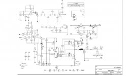
Ok make an analysis; the output inductor cut of frequency in your shematic? L=200uH C= 1.5uf R=4ohms. One can easily guess, it is for a sw amplifier. The other shematics(one FB and the other HB) that I am refering have 50uh/0,68nf combination and uses IR2010S drivers. Againg calculate the output filter cutoff frequency. If you are a really RF desing engineer these are really quick calculations for you.
I am also not an engineer and I have PhD in Chemistry.
You ask a question and the DIYers here tried to help you. Every one said his/her own ideas for your quesiton. I think some of these will help you.
Please do not offend someone.
Regards
I know the site you are refering and also I have these shematics. If I am not wrong there should be some another shematics there(in same topic) which is more logical in your case.
Ok make an analysis; the output inductor cut of frequency in your shematic? L=200uH C= 1.5uf R=4ohms. One can easily guess, it is for a sw amplifier. The other shematics(one FB and the other HB) that I am refering have 50uh/0,68nf combination and uses IR2010S drivers. Againg calculate the output filter cutoff frequency. If you are a really RF desing engineer these are really quick calculations for you.
I am also not an engineer and I have PhD in Chemistry.
You ask a question and the DIYers here tried to help you. Every one said his/her own ideas for your quesiton. I think some of these will help you.
Please do not offend someone.
Regards
- Status
- This old topic is closed. If you want to reopen this topic, contact a moderator using the "Report Post" button.
- Home
- Amplifiers
- Class D
- Ir2104+ Irf540