Hi everyone:
I've had to take a very long extended break, but now am ready to try to finish up some work on my Chipamp LM3886 dual mono project.
Question: What are the components at the beginning of the circuit? IT was marked as a Zobel network, but IIRC, Allan from (the now defunct) Chipamp.com said it was an input RC filter. Is that correct? Is it a LP filter? HP filter? Does anyone know?
Thanks
Chipamp.com said it was an input RC filter. Is that correct? Is it a LP filter? HP filter?
At the input, it's a low pass filter, if the capacitor is a small value and is connected to ground.
It's a high pass filter if the cap is a large value and is in series with the signal.
You also can have both, like this. http://www.circuitbasics.com/wp-con...6-Circuit-Schematic-with-Diode-2-1024x862.png
Last edited:
Thanks. The cap, Cz appears to be a Vishay 100nF 63V. I'm guessing (no knowledge at all of electronics) that this is a "small" value?
I have almost no knowledge/experience with electronics, so I'm having a hard time being sure of the resistor (Rz) colours. It looks to me like Orange Violet Gold Gold. When I tested it on two diff. boards with a DMM, it measured 2.8 ohms. As for ground, the two components were never added to the Chipamp.com schematic. And I don't know how to tell just by looking at the PCBs.
Can anyone confirm these values?
Is that a LP or HP filter? (I don't know what high or low values would be, due to my lack of knowledge).
Thanks
Last edited:
Thanks. The cap, Cz appears to be a Vishay 100nF 63V. It looks to me like Orange Violet Gold Gold.
it measured 2.8 ohms. Is that a LP or HP filter?
The 100nF is a relatively large value, and is a coupling capacitor, forming a high pass (bass cut) filter.
A Orange-Violet-Gold-Gold resistor should be 3.7R with 5% tolerance.
Okay, so....have I got the colours wrong or ?? Here's the LiquidAudio page on which he shows building his kit
LM3886 Chip Amp / gainclone amplifier construction project
There is a closeup photo captioned "Here's a reverse view..." showing the input resistor Rz and its colours.
Can you tell from that photo what colours those are? It's hard to see on my board.
LM3886 Chip Amp / gainclone amplifier construction project
There is a closeup photo captioned "Here's a reverse view..." showing the input resistor Rz and its colours.
Can you tell from that photo what colours those are? It's hard to see on my board.
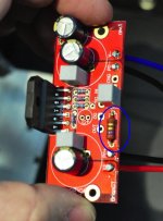
You can always follow the traces on the board. Show where it connects. I bet that resistor and the grey 100 nF cap next to it are connected in series. One end of the series connection connects to pin 3 (output) of the LM3886 and the other end connects to ground. That'd be the Zobel network.
Tom
Tom
Yeah, no schematic. I was told by Allan @ Chipamp that in spite of the designation "z" for Zobel, neither of these components constituted a Zobel network, that they were an input RC filter, but my knowledge level is zero. Can anyone else be sure?
It seems Allan has given you bad information. those two components (Rz and Cz) are a Zobel on the output.
Those chipamp boards do not have a spot for an input RC filter. However, you could substitute a capacitor for R1 and form one. The lead spacing might be an issue though.
The miniDSP units have an output capacitor anyways, so you would not need this RC input filter for DC blocking. But, I assume you know that.
Dave.
- Status
- This old topic is closed. If you want to reopen this topic, contact a moderator using the "Report Post" button.
- Home
- More Vendors...
- Chipamp
- input RC