Any one built the bridged/parallel LM3886 using the National Semi ap notes? Here is a layout, constructive comments welcome....ap notes located here:
http://www.national.com/pf/LM/LM3886.html
http://www.national.com/pf/LM/LM3886.html
Attachments
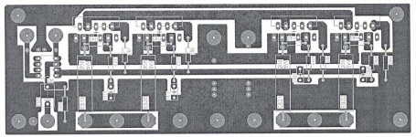
BPA200
Your mute pin is open also")
what cap value are you useing on your NFB? looks like a small film consider useing a high quality 47uf electrolitic bypassed with a 1uf metal film also run the cap/film first and the resistor to ground.
Use .1% resistors or hand match 1%'s to .01% or better.
I found 1.5 ohm output resistors to be the best choice and they also need to be 1% or better or hand matched.
Are you useing a DRV134 or similar? or a differencial input? noise rejection becomes an issue with a DRV use a non-inv. buffer.
Good Luck, I love my BPA's
Your mute pin is open also
what cap value are you useing on your NFB? looks like a small film consider useing a high quality 47uf electrolitic bypassed with a 1uf metal film also run the cap/film first and the resistor to ground.
Use .1% resistors or hand match 1%'s to .01% or better.
I found 1.5 ohm output resistors to be the best choice and they also need to be 1% or better or hand matched.
Are you useing a DRV134 or similar? or a differencial input? noise rejection becomes an issue with a DRV use a non-inv. buffer.
Good Luck, I love my BPA's
Mute
Ap notes show no connection to mute. But I have seen boards with connections to mute.
Resistor values are per ap notes. Err....1.5 OHMS?...you may want to read page 11 of the application notes....
As for inverting input - check carefully - the inputs on the right side of board go into negative - positive on the left as per the ap notes...if all chip connections were identical then one would have to be inverted...this layout is the least complicated. Did you make your own boards or use prefabed pcbs...? Do you know which topology your BPAs use ?
BPA200
The app notes give you a base circuit its not always optimal or preffered. With the mute pin open you will get no sound 22Kohm resistor to the neg. rail, depending on Vs 20ma needs to be present at pin to turn on the chip.
BPA units can be very complicated, layout is of utmost importance, you will also find that feeding the circuit with a phase splitter like a properly implemented DRV134 with a buffer will yield better current control and sonics, you will always get different sonic and preformance from the chips being inv. on one side and non-inv. on the other just the nature of the beast.
again good luck, I have built many BPA units and gone through alot of parts and had alot of fun while doing it.
The app notes give you a base circuit its not always optimal or preffered. With the mute pin open you will get no sound
22Kohm resistor to the neg. rail, depending on Vs 20ma needs to be present at pin to turn on the chip. BPA units can be very complicated, layout is of utmost importance, you will also find that feeding the circuit with a phase splitter like a properly implemented DRV134 with a buffer will yield better current control and sonics, you will always get different sonic and preformance from the chips being inv. on one side and non-inv. on the other just the nature of the beast.
again good luck, I have built many BPA units and gone through alot of parts and had alot of fun while doing it.
BPA200
PS I make all my own boards.
1.5 ohm output resistors will only drop your voltage by .5 to 1V depending on Vs, but offer a 1.5* gain on current matching, helping the chip work together will yield the biggest preformance and sonic gains, in BPA units current flow and dissipation are your biggest problems and without servo's become a very big obstruction to overcome. from what I have seen and measured most non-servoed designs will dissipate 1.5 to 3* per chip there Idle current reduceing the output power available and the chip life span.
PS I make all my own boards.
1.5 ohm output resistors will only drop your voltage by .5 to 1V depending on Vs, but offer a 1.5* gain on current matching, helping the chip work together will yield the biggest preformance and sonic gains, in BPA units current flow and dissipation are your biggest problems and without servo's become a very big obstruction to overcome.
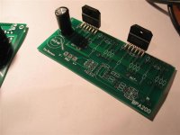
from what I have seen and measured most non-servoed designs will dissipate 1.5 to 3* per chip there Idle current reduceing the output power available and the chip life span.i had made these. work well. using dual opamp to first half non-inv buffer then drives 2 parallel non-inv chips and inverting half of opamp to drive other two paralle chips. too ignorant to state flaws or measurement of the approach.
next thing with to try is using opamp and the parallel chip branches inside feedback loop - lightly discussed in another thread.
next thing with to try is using opamp and the parallel chip branches inside feedback loop - lightly discussed in another thread.
Attachments
BPA200
QUOTE:
The app notes give you a base circuit its not always optimal or preffered. With the mute pin open you will get no sound 22Kohm resistor to the neg. rail, depending on Vs 20ma needs to be present at pin to turn on the chip.
Thanks!...no sound would be a problem Since you have made your own boards do you have any pcb layouts you are willing to share? Not really interested in reinventing the wheel with the BPA200. The main interest in using the LM3886 was lower part count and advailability of power transformers over other designs. The lower LM3886 supply voltages allow easier LM317/337 voltage drop to opamp levels for a Linkwitz transform circuit. Reliability (especially long term) are important also, over what time period have you been operating BPA designs ?
QUOTE:
The app notes give you a base circuit its not always optimal or preffered. With the mute pin open you will get no sound 22Kohm resistor to the neg. rail, depending on Vs 20ma needs to be present at pin to turn on the chip.
Thanks!...no sound would be a problem
Since you have made your own boards do you have any pcb layouts you are willing to share? Not really interested in reinventing the wheel with the BPA200. The main interest in using the LM3886 was lower part count and advailability of power transformers over other designs. The lower LM3886 supply voltages allow easier LM317/337 voltage drop to opamp levels for a Linkwitz transform circuit. Reliability (especially long term) are important also, over what time period have you been operating BPA designs ?Re: BPA200
20ma? the datasheet says .5mA
22k does sound reasonable though.
-Nick
zlast said:QUOTE:
The app notes give you a base circuit its not always optimal or preffered. With the mute pin open you will get no sound 22Kohm resistor to the neg. rail, depending on Vs 20ma needs to be present at pin to turn on the chip.
20ma? the datasheet says .5mA
22k does sound reasonable though.
-Nick
- Status
- This old topic is closed. If you want to reopen this topic, contact a moderator using the "Report Post" button.
- Home
- Amplifiers
- Chip Amps
- Bpa200 Lm3886