When I mean "matched" I do mean output level or volume. I don't think it is your card causing the problem. Try increasing the resistor from the input to ground to around 75k-100k and see if that helps. What value cap do you have on the input? When I tried small voltage value film caps (100V)in my experiments, the sound was thin and anemic.
ksProject drivers?!?
ksProject drivers?!?
Bridges to Babylon
Here's how the bridges look. I placed the diodes in a way to achieve minimum connections. Two 4.7u N caps are on ea. rail between diodes.
Philo said:.
Peter, could you post a pic of your rectifier build? Did you make a PCB for them like your Alephs?
Here's how the bridges look. I placed the diodes in a way to achieve minimum connections. Two 4.7u N caps are on ea. rail between diodes.
Attachments
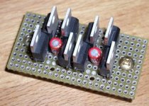
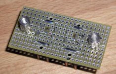
K with A connect on the outside and this is where the 4 wires from secondaries go (through the large holes). Eight pins in the center are for 8 wires going to the amp. Two K and two A of four diodes pairs are connected with short wires on a components side. This is mounted directly to the rear panel of PS enclosure. I didn't really see a reason to make PCBs for that.")
Attachments
Hi!
I do not use any cap right now... DC offset is always somewhere between 20 mV - 200 mV (according to how I wire the whole resistor / signal stuff).
kxProject is an open source implementation of soundcard drivers for the emu101k soundcard series, for example the audigy. It lets you control every single aspect of your card, and enables a totally free programmable (with already a lot of pre-fabricated modules) DSP on your card... I use it to actively control my system (crossover with any slope you like, compressor, equalizing...)
You can find it under www.kxproject.com
I will try increasing the resi to ground later on - if I at least understood it correctly, the volume should go up if I increase the resi to ground, while on the other hand decreasing the resi in series to input...?
Hope it works...
Bye,
Arndt
Philo said:When I mean "matched" I do mean output level or volume. I don't think it is your card causing the problem. Try increasing the resistor from the input to ground to around 75k-100k and see if that helps. What value cap do you have on the input? When I tried small voltage value film caps (100V)in my experiments, the sound was thin and anemic.
ksProject drivers?!?
I do not use any cap right now... DC offset is always somewhere between 20 mV - 200 mV (according to how I wire the whole resistor / signal stuff).
kxProject is an open source implementation of soundcard drivers for the emu101k soundcard series, for example the audigy. It lets you control every single aspect of your card, and enables a totally free programmable (with already a lot of pre-fabricated modules) DSP on your card... I use it to actively control my system (crossover with any slope you like, compressor, equalizing...)
You can find it under www.kxproject.com
I will try increasing the resi to ground later on - if I at least understood it correctly, the volume should go up if I increase the resi to ground, while on the other hand decreasing the resi in series to input...?
Hope it works...
Bye,
Arndt
Hi!
I just read in another thread (the one with the "humming" GC - wonder how a GC could have picked up Portishead ) that someone got rid of the hum when he disconnected signal ground from star ground...
But isn't signal ground supposed to go to star ground?
Or can I maybe put a cap beteen signal ground and star ground - would that help?
I can see that GC is a neverending story as far as modifications are concerned ...
I just read in another thread (the one with the "humming" GC - wonder how a GC could have picked up Portishead
) that someone got rid of the hum when he disconnected signal ground from star ground...But isn't signal ground supposed to go to star ground?
Or can I maybe put a cap beteen signal ground and star ground - would that help?
I can see that GC is a neverending story as far as modifications are concerned ...
Call me confused...
Just tried a cap from input to ground, DC offset went up to about 15 V
After that I desoldered the cap, and put my first "original" humming configuration back in - just the 10 ohms resi in series to signal, no cap, no resi to ground, hooked everythin back up,
THE HUM IS GONE But don't know why - yesterday and today I only resoldered and resoldered and resoldered the resistors from signal, and the 1.7 cm long cable connecting it to input on the IC... nothing else
But another weird thing: It still plays too quiet! When I first listened to the GC and noticed the hum, the volume level was totally OK, now I have to put volume sliders to max to get at least adequate volume for my room...
So, back to soldering
Btw, just measure (I hope I did it right) impedance from the input (disconnected from amp, measured between signal pin and shield of the cinch connector), it was 79 ohms. Could that information help?
Just tried a cap from input to ground, DC offset went up to about 15 V
After that I desoldered the cap, and put my first "original" humming configuration back in - just the 10 ohms resi in series to signal, no cap, no resi to ground, hooked everythin back up,
THE HUM IS GONE
But don't know why - yesterday and today I only resoldered and resoldered and resoldered the resistors from signal, and the 1.7 cm long cable connecting it to input on the IC... nothing elseBut another weird thing: It still plays too quiet! When I first listened to the GC and noticed the hum, the volume level was totally OK, now I have to put volume sliders to max to get at least adequate volume for my room...
So, back to soldering
Btw, just measure (I hope I did it right) impedance from the input (disconnected from amp, measured between signal pin and shield of the cinch connector), it was 79 ohms. Could that information help?
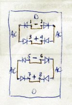
Here's the schematic of my bridge. Pins 1-4 create nodes on the DC side of the bridge for one rail; the other four pins, for the other rail. The 4.7 N caps (2 of them) are connected between pins 1 and 3, and 5 to 7. There are 8 wires from PS, and the ones from odd number pins go to one channel and the ones from even number pins got to the other channel. The grounds for both channels are connected on that board.
There are additional 4 x 1000u/50V caps in the amp (2 per chip). I didn't put any small caps across the diodes. First, there is not enough space, second pinkmouse tried it and reported that they soften or smear the highs. Another observation I made: I tried to use a nice 10A, Swiss made AC line filter with the PS and I didn't like it. I observed similar effects as PM reports.
There are additional 4 x 1000u/50V caps in the amp (2 per chip). I didn't put any small caps across the diodes. First, there is not enough space, second pinkmouse tried it and reported that they soften or smear the highs. Another observation I made: I tried to use a nice 10A, Swiss made AC line filter with the PS and I didn't like it. I observed similar effects as PM reports.
Attachments
Hi!
I'm plainly getting nuts with this stuff !
!
Maybe it WAS a bad soldering point what produced the hum / and the low volume...
It worked alright some hours ago (even without any resistor from signal to ground, but I decided to put one in, nevertheless). No hum, just plain music regardless of volume, and amp not getting hot
Then I soldered the second channel (in the same case, using the same power connection - I know, not the best way, but...)
I hooked it to supply and signal cables, and the second channel worked also well (and, important, the first channel still worked allright).
Then I screwed my case shut (one of those small heatsink cases conrad sells), put the supply and the GC in my rack, installed cables, and now the grande finale:
Music is very distorted even at low levels (while no noise at all is audible when I simply stop playing the music), and the GC got very hot... Oh No !
I unscrewed the top of the case, checked everything (remember, I did not change anything but screwing on the top of the case), can't find anythin. And the noise / heat won't go away, regardless what I tested (just one channel connected at all, both channels connected to supply but only one to signal and so on).
This drives me mad ! There must be demons / poltergeists around my flat
  !!
!!
I've run completely out of things to try (but taking everything apart again, and rebuild it from scratch, which I do not want to do...)
Why me?
Frustrated bye,
Arndt
I'm plainly getting nuts with this stuff
!Maybe it WAS a bad soldering point what produced the hum / and the low volume...
It worked alright some hours ago (even without any resistor from signal to ground, but I decided to put one in, nevertheless). No hum, just plain music regardless of volume, and amp not getting hot
Then I soldered the second channel (in the same case, using the same power connection - I know, not the best way, but...)
I hooked it to supply and signal cables, and the second channel worked also well (and, important, the first channel still worked allright).
Then I screwed my case shut (one of those small heatsink cases conrad sells), put the supply and the GC in my rack, installed cables, and now the grande finale:
Music is very distorted even at low levels (while no noise at all is audible when I simply stop playing the music), and the GC got very hot... Oh No
!I unscrewed the top of the case, checked everything (remember, I did not change anything but screwing on the top of the case), can't find anythin. And the noise / heat won't go away, regardless what I tested (just one channel connected at all, both channels connected to supply but only one to signal and so on).
This drives me mad
! There must be demons / poltergeists around my flat !!I've run completely out of things to try (but taking everything apart again, and rebuild it from scratch, which I do not want to do...)
Why me?
Frustrated bye,
Arndt
Bricolo said:does this mean "I'm too lazy to try" ?
This may as well apply to you.
But indeed you are right.
Peter Daniel said:
This may as well apply to you.
But indeed you are right.
this will apply to me too, in some days
but first, I'm trying to get rid of this oscillation problem.
A friend comes with his scope in a few days, I hope this will help
and after that, I'll second you for tweaking
PS: have you looked at my gainclone preamp thread?

BricoloFor qpapag: I was told to wire +In with it's own wire to the star ground, and then in+mute and stdby-gnd together to ground. OK so far
But where do I connect my PSU bypass caps? One side to +PWVs, and the other side to ground, but wich pin? +in, or mute and stdby?
I think I'll leave the 0.1uF caps where they are (they are soldered directly to Vs (+ and -) and I'll add the 200uF ones directly on the PWVs pins) but as sayd before, I don't know where to get the mass for those
You don't have to be confused. Just return everything to star ground with it's own wire. To make it easier:
1.Pin 1
2.Input's plug ground
3. Pin 3
4. Pin 4.
5. Each by-pass capacitor
6. Speakers (-)
7. PSU's ground.
(1-4 can be done with thin wire, like AWG 28)
Try to place Star ground not far away from the chip. Sometimes i find it beneficial (less hum) to connect 2 & 3 not directly to star ground, but through a 10 Ohm resistor (suggested by Mr. Cherry). The metal chassis is mandatory to be connected to safety earth. Whether you will connect safety earth with star ground, is something you have to deside by experimentation. You may use a switch ("ground lift" in audio jargon), for to see which case gives the less hum.
Good luck
Regards
George
- Status
- This old topic is closed. If you want to reopen this topic, contact a moderator using the "Report Post" button.
- Home
- Amplifiers
- Chip Amps
- This is not just another gainclone