Peter Daniel said:The DC offset is usually 28mV in all the amps I built, both channels very close in that value and non inverting input shorted to ground.
Yup. That's been my experience as well over the years. Which is why I thought it rather odd that one channel should have such a large difference relative to the other. You'd pretty much have to end up with two devices each at opposite ends of the tolerance range. Which I suppose is possible, but rather odd just the same.
se
Just checking
How much Watts should 1 get with 22Vdc on the rails and Peter's "Minimized " model?
I put together his circuit yesterday with real cheap components and are getting worried now. This little "lightweight" assembly of components seems to sound almost better then my "heavyweight" Aleph30. Obviously it is not burnt in yet, so I don't know how it is going to end up. All components and trafo are in 1 box, offset are 24 and 27mV, there are no humming or any other interferance anywhere and it was only $30, including LM3875 from RS.
Hamish said:should be a shade under 30watts/8ohm, if my maths is correct (probably not). somewhere around there anyway.
Per channel?
Re: Just checking
About 22 W into 8 ohms
dave
JDeV said:How much Watts should 1 get with 22Vdc on the rails and Peter's "Minimized " model?
About 22 W into 8 ohms
dave
Attachments
Peter D. has mentioned that his 18V supply sounds better than his 24V.
Can the reason be that the chip is "linear" up to around +/-28V dc, so when you (like I do) use 24V trafo`s the output power in 4 and 6ohms decrease.
By the graph it looks like my GC (running +/-36V dc) puts out around 60W in 8ohm, 12W in 6ohm and <10W in 4ohhm...
It looks like the chip behaves more like an ordinary amp. as long as the voltage is below +/-28V dc.
Just a tought....
JDeV said:Thanx for the effort Dave
I measured the output yesterday by connecting a fat 8ohm resistor and applying a 200Hz sine wave. It started to clip at 10.6v Trms. Now if I calculate correct:
Pout=V²/R
=10.6²
--------
8
=14 Watt
What do I miss?
Your math's fine.
The 22 volts you mentioned previously that you measured on the rails, was that the unloaded voltage? And are you using just 1,000 uF of filter capacitance?
Be aware that under load your transformer's voltage will be less than the unloaded voltage. What's the regulation figure for the transformer you're using? Also, if you're using just 1,000 uF of filter capacitance that those caps are going to be drawn down quite a bit between refresh cycles so your average power supply voltage will be less as well. Both instances mean that your amp will start to clip sooner compared to what you would expect basing your expectations on the unloaded rail voltages.
se
Steve Eddy said:
Your math's fine.
The 22 volts you mentioned previously that you measured on the rails, was that the unloaded voltage? And are you using just 1,000 uF of filter capacitance?
se
Indeed, 22V on rails while unloaded and only 1,000uF. I plan to fit a pair of 10,000uF and also some other PSU improvements once current setup burnt in, to be able to do reasonable comparison between "before" and "after."
2002tii said:Peter D. has mentioned that his 18V supply sounds better than his 24V.
....
Can the reason be that the chip is "linear" up to around +/-28V dc, so when you (like I do) use 24V trafo`s the output power in 4 and 6ohms decrease.
This is what my recommendation of 18-0-18 trafos is based on.
dave
planet10/whose chips are still in their anti-static bags
2002tii said:Peter D. has mentioned that his 18V supply sounds better than his 24V.
I did not say it sounds better with lower voltage. I said it produces more bass. Depending on the rest of the system, it may change the tonal balance and be actually something unwanted. The person who is using my first gainclone, said that he prefers the sound of the higher voltage supply, which is using Plitron 400VA , 22-0-22 V transformer. This transformer is so powerfull that I actually see 24 V all the time because of regulation factor, which doesn't apply here.
Hi,
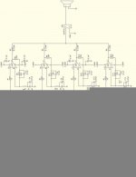
There's a paralell version schma.
Check this
http://www.fortunecity.com/underworld/tetris/649/lm3875x4d.jpg
cheers
Coffin
There's a paralell version schma.
Check this
http://www.fortunecity.com/underworld/tetris/649/lm3875x4d.jpg
cheers
Coffin
Attachments
Mats J said:If you take four(4) inverted GC's, parallel pairs (so you then have two amps), remove the pots and feed each parallel pair with a phase from a Jensen Transformer model JT-10KB-D. Would that work as kind of a BPA-200/High power GC?
Basically, yes. But why use a 4:1 stepdown transformer? Just use an 11P-1. You'll need to use a pair of 5k resistors in series across the output taking your ground reference from the node between the two resistors.
se
Peter Daniel,
what kind of power plugs do you use here?
http://www.diyaudio.com/forums/showthread.php?postid=104281#post104281
Would it not be good idea to use XLR's for power?
what kind of power plugs do you use here?
http://www.diyaudio.com/forums/showthread.php?postid=104281#post104281
Would it not be good idea to use XLR's for power?
- Status
- This old topic is closed. If you want to reopen this topic, contact a moderator using the "Report Post" button.
- Home
- Amplifiers
- Chip Amps
- This is not just another gainclone