Peter, awsome work with that gainclone.
What if you add some blue leds in the middle clear acrilyc part, it will make its sides blue, and reflect in the fins of that heatsink.
When its dark, the effect should be impressive.
Just a thought I had while looking at your design.
What if you add some blue leds in the middle clear acrilyc part, it will make its sides blue, and reflect in the fins of that heatsink.
When its dark, the effect should be impressive.
Just a thought I had while looking at your design.
Bricolo:
I've built several 7294 and find to be only intolerant of layout, otherwise they are extremely sturdy chips with pretty good chances of working out of the box.
You might try first building the datasheet circuit and then working your way up (down?) to an inverted GC type of schematic. The other thing I would recommend is a resistor for impedance matching (around 8.2K?) from the + input to ground, and then a cap between the pot wiper and the 10K resistor, as well as a 100K or so pot.
And oh, yeah, a bigger heatsink please. What you've specified may not be enough for the 7294 even at idle... Check the datasheets for recommended h/s specs.
how to build this Gainclone?
My oncologists thinks it would be benificial for me to pick up some kind of project while undergoing chemotherapy. MY mind immediately wandered to my stereo equipment. While I currently run an Adcom GFA-6000 and just picked up a pair of Dynaco St-120;s (which I plan to mod) . I've been increasingly interested in building a Gainclone. Unfortunately finding shemtics and building instuctions that are easy to undertand seems to be impossible. I had initially settled on the RJM Gainclone but several posts around have pointed people away from this as a first project. Can anyone reccomend a fairly easy to build high quality gainclone to build? I'd like to make something in the 50w rms area...something that can fit in my present set up fairly easily. Any help would be appreciated.
My oncologists thinks it would be benificial for me to pick up some kind of project while undergoing chemotherapy. MY mind immediately wandered to my stereo equipment. While I currently run an Adcom GFA-6000 and just picked up a pair of Dynaco St-120;s (which I plan to mod) . I've been increasingly interested in building a Gainclone. Unfortunately finding shemtics and building instuctions that are easy to undertand seems to be impossible. I had initially settled on the RJM Gainclone but several posts around have pointed people away from this as a first project. Can anyone reccomend a fairly easy to build high quality gainclone to build? I'd like to make something in the 50w rms area...something that can fit in my present set up fairly easily. Any help would be appreciated.
you say they are intolerant, what kind of problem did you have with yours?sangram said:Bricolo:
I've built several 7294 and find to be only intolerant of layout, otherwise they are extremely sturdy chips with pretty good chances of working out of the box.
You might try first building the datasheet circuit and then working your way up (down?) to an inverted GC type of schematic. The other thing I would recommend is a resistor for impedance matching (around 8.2K?) from the + input to ground, and then a cap between the pot wiper and the 10K resistor, as well as a 100K or so pot.
And oh, yeah, a bigger heatsink please. What you've specified may not be enough for the 7294 even at idle... Check the datasheets for recommended h/s specs.
Have you tried the inverting configuration?
At iddle it is +-30mA, so with +-25V, that wouldn't even be 1W heat dissipation


For those of you that might find the gc a little bit dry and light in the bass I can report that bypassing with a couple uf film caps either before the bridge or parallel to the main chip caps works a dream. I have made quite a few A/B tests on two different gc's and the result is quite obvious. There is what I might describe as a "loudness switch" -for lack of a better term- that quite noticeably gives more fullness to the bass and a touch more in the treble. This makes the music more "lively". As I said this is a personal thing and if your gear is perfectly balanced as it is you might find this a bit over the top.I did notice an almost imperceptible lessening of precision and midrange neutrality but not really important. I used 2,2uf MKP audyn caps but I have noticed exactly the same effect with the same value polycarbonate.
Just to recap: there is a very noticeable difference when doing this but may not be to everybodys taste.
Just to recap: there is a very noticeable difference when doing this but may not be to everybodys taste.
rwagter said:Jasonruiz,
just take the schematic from post 722 build it with standard components a graduatly replace for quality ones.
It will bring a small on ones face "building"such a rediculous simple but fine sounding amp.
Ralph
Check the post 882 and 883 of this thread http://www.diyaudio.com/forums/showthread.php?s=&threadid=9112&perpage=15&pagenumber=59 for instructions and schematic.
Jason
Good luck and never give-up. Modern chemotherapy protocols are doing wonders, believe me. And when they turn your mood down, switch to the theads of this site and let your mind fly away for a while. Everything will be alright again in a few months. You will see. Just trust your doctors and believe in the powers that are hidden in your body and your mind.
Regards
George
Bricolo
I have build TDA 7294 the way you did (post # 1038), except :
1. no potentiometer at the input (10K directly from input jack to pin 2, 220k from pin 14 to pin 2, pin 3 to ground).
2. except from 0.1 mF at +V and -V pins, at least 100mF (i used 220mF) directly at these pins. Otherwise, there was oscillation easily seen on the scope. Data sheets recommend 1000mF on power pins, and they are right.
3. The minimum finned heatshink i used was 50x30x20mm. It was o.k. for idle, but not for anything else. Go for a minimum 90x70x35mm for playing music.
4. All grounds with separate wires to star ground.
I still prefer the "sound" of TDA7294 to LM 3886, either inverted (as above), or non inverted as per data sheets, even utilising one symmetrical power supply. If you get into the trouble to feed the low power section (pins 7,8) from a separate PSU, then the difference becomes biig.
Regards
George
For the PS bypass caps, did you use 220mF or 220µF?gpapag said:Bricolo
I have build TDA 7294 the way you did (post # 1038), except :
1. no potentiometer at the input (10K directly from input jack to pin 2, 220k from pin 14 to pin 2, pin 3 to ground).
2. except from 0.1 mF at +V and -V pins, at least 100mF (i used 220mF) directly at these pins. Otherwise, there was oscillation easily seen on the scope. Data sheets recommend 1000mF on power pins, and they are right.
3. The minimum finned heatshink i used was 50x30x20mm. It was o.k. for idle, but not for anything else. Go for a minimum 90x70x35mm for playing music.
4. All grounds with separate wires to star ground.
I still prefer the "sound" of TDA7294 to LM 3886, either inverted (as above), or non inverted as per data sheets, even utilising one symmetrical power supply. If you get into the trouble to feed the low power section (pins 7,8) from a separate PSU, then the difference becomes biig.
Regards
George
Directly on the pins, like I did with my 0.1µF? And then bigger ones on the diodes bridges?
I'm not sure, but IMO datasheets even recommends 1000µF on a DC power supply (we all use 1000 on an AC sypply)
when you say "the heatsink was ok for iddle", was it warm or reasonably hot even at iddle?
Since you're talking about the low and high power pins, did you wire them indidivually to the power supply, or with one cable, and a short wire from VS to PWVs?
Did you use 220µF for each, or for the pair?
Bricolo
You are right. Bypass caps are 220uF. And Yes, directly on the pins. When i used one symmetrical PSU (which was 30mm away from the TDA7294), i used one wire and one 220uF cap per polarity for both pins. If you have enough space, AND if your PSU is quite away from the TDA7294 (or anyother chip), increase the value of these caps, up to 1000uF. At the PSU now, you may start with a series 2R2/5W after the bridge, then 100uF shunt, then a series 2R2/5W, then 1000uF shunt, then a series 2R2/5W, then 2200uF. So you have a 3 step filter, with low charging current spikes at the bridge, and quite low and smooth ripple.
I don't have much money to spend, so i use only "normal" components. What i have noticed though, is that with toroidal x-formers, the 50Hz waveform of the secondary, was clipping (even with no load), and this was producing an edgy sound compared to the sound of the amp driven by the same PSU but with E-I x-formers. I attributed this saturation to the high permeability of the toroidal core. I found a guy who was winding toroidals. I bought some of his and they had the same problem. Then i asked him to wind the primary with 10% more turns/volt. When i checked these toroidals, they had a nice sinewave and the amp had a nice sound. So be cautious with x-formers. It is not only their voltage and nominal wattage that is important.
The small heatsink was warm (around 40 d. Celcius) at idle.
Regards
George
I also tried EI transformers with my GC and I was actually expecting it to sound better. The transformers were 200W, 18V AC and I used one per rail. I then compared to my reference 400W Plitron with 22-0-22 secondaries, and Plitron sounded better to my surprise. It was also much quieter. The same goes for 18-0-18v Plitron.
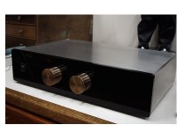
Just another integrated Gainclone
This is it. My humble attempt. Laugh if you will, but it makes me happy.") . Four inputs wired with 21AWG silver wire (easy, Frank
. Four inputs wired with 21AWG silver wire (easy, Frank  ) and I added the BG4.7 Ntypes. How long do you think it took your input caps take to break in Peter? I had the copper shield all cut when I decided to listen to it as it sits and since it was dead quiet, I left it as you see it.
This is it. My humble attempt. Laugh if you will, but it makes me happy.
. Four inputs wired with 21AWG silver wire (easy, Frank ) and I added the BG4.7 Ntypes. How long do you think it took your input caps take to break in Peter? I had the copper shield all cut when I decided to listen to it as it sits and since it was dead quiet, I left it as you see it.Attachments
- Status
- This old topic is closed. If you want to reopen this topic, contact a moderator using the "Report Post" button.
- Home
- Amplifiers
- Chip Amps
- This is not just another gainclone