Re: Re: Diodes
FC should be the same. FA is discontinued and FC is the follow up. If you compare the datasheets, you will see the specs
are the same...
(though minor manufacturing differences could have occurred)
Fedde
giolight said:
The FA Panasonic are the same as FC with longer lifetime or just different series?
Giorgio
FC should be the same. FA is discontinued and FC is the follow up. If you compare the datasheets, you will see the specs
are the same...
(though minor manufacturing differences could have occurred)
Fedde
CONRAD CASES
Who sells those cases?
Carlos
fedde said:I use the same Conrad case for my brand new Nonoz II DAC...
Who sells those cases?
Carlos
Re: CONRAD CASES
")
See www.conrad.com...
Fedde
Err.. Conrad !?carlmart said:
Who sells those cases?
Carlos
See www.conrad.com...
Fedde
Bi-Polar Gainclone Suggestion
There has been some discussion lately about the merits of inverting operation VS non-inverting operation for the GainClone circuit, so perhaps it is prudent to show that an opamp circuit can be switched either way as below.
I know the circuit given is configured for X1 gain, but circuit values can be suitably changed.
I did also see a similar circuit in WW/EW circuit years ago that used a pot instead of a switch as the polarity selector.
This gave +1 through 0 through -1 gain and polarity control, and was described as being useful for selecting reverb unit return signal polarity, but alas I forget the finer details - anybody have that circuit to hand ?.
Either of these two circuits implemented correctly may be suitable to give the luxury of choice of GainClone operating mode.
This circuit is of course perfectly suitable for line level polarity control, and could easily be incorporated into a preamp or cdp output stage.
Eric.
Attachments
fedde said:I use the same Conrad case for my brand new Nonoz II DAC...
And I use the same for my GC except it is the slightly higher size (70 mm I believe). It is a pretty nice case actually for those who do not have a proper workshop like me (kitchen table...).
CONRAD CASES
Can you specify type or model? I went into Conrad's site but it's not easy to get to which models they carry.
Carlos
fedde said:
Can you specify type or model? I went into Conrad's site but it's not easy to get to which models they carry.
Carlos
Re: CONRAD CASES
Already in this thread once:
Conrad article 522945 and:
http://www.diyaudio.com/forums/showthread.php?postid=108716#post108716
carlmart said:
Can you specify type or model? I went into Conrad's site but it's not easy to get to which models they carry.
Carlos
Already in this thread once:
Conrad article 522945 and:
http://www.diyaudio.com/forums/showthread.php?postid=108716#post108716
does anyone know the exact amount of heat each chip creates at full volume? (a maximum)
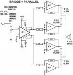
i was thinking of using this diagram to bridge and parellel 4 together (4 chips) per channel and tri amp them
this would give me 224 watts per channel, per speaker and then i was going to make a seperate sub woofer driver (posibly with the same chips) and then use 4 car batteries in series to give me +-24v (approx.) and put it in my car (when i get one).
sound cool?
i was thinking of using this diagram to bridge and parellel 4 together (4 chips) per channel and tri amp them
this would give me 224 watts per channel, per speaker
and then i was going to make a seperate sub woofer driver (posibly with the same chips) and then use 4 car batteries in series to give me +-24v (approx.) and put it in my car (when i get one).sound cool?
Attachments
I tested my gainclone today
results: a little hum, and the output level is quite low (I wasn't using a pot, and the volume was a little more loud than a normal listening volume)
I used peter's shematic, with a 220VA 2*18V transformer, and a TDA7294 (10K and 220K resistors)
results: a little hum, and the output level is quite low (I wasn't using a pot, and the volume was a little more loud than a normal listening volume)
I used peter's shematic, with a 220VA 2*18V transformer, and a TDA7294 (10K and 220K resistors)
I tried with a cd player (no adjustable output), and I had the good idea to put noise blocking pads in my ears before
A couple of years ago, I bought a cheap 100K pot, put it in a very small box with some wires and phono plugs. I use it when I want to couple source components to a power amp for testing and it's one of my useful tools.
Bricolo said:Is it normal that the chip goes very hot (on a small heatsink, I admit) with no signal input?
No! Probably oscillation or so. Even with medium listening levels my chips stay cool on my 92-93 dB/W tannoys.
Fedde
fedde said:
No! Probably oscillation or so. Even with medium listening levels my chips stay cool on my 92-93 dB/W tannoys.
Fedde
with what kind of heatsink?
Check post 45 in this thread. Whole light bulb procedure explained.
http://www.diyaudio.com/forums/show...highlight=oscillation light bulb&pagenumber=3

Marc
http://www.diyaudio.com/forums/show...highlight=oscillation light bulb&pagenumber=3
Marc
- Status
- This old topic is closed. If you want to reopen this topic, contact a moderator using the "Report Post" button.
- Home
- Amplifiers
- Chip Amps
- This is not just another gainclone