power operational amplifiers (gainclones)
Good evening beloved torture-loving fellows! Yesterday night
i managed to finish reading this thread and most of it's links.
I have to thank you all for your contribution to this topic. You
see, even the latest model of the "human" seems to operate in
class B, with a lot of cross-over spikes at the area of transition
from the upper device(human 1) to the lower device (human 2).
Besides, it is very difficult to find truly matched devices.
Thus, arguments will always exist!
I have used power op-amps in the past. Cronologically:
1.National LM1875
2.National LM12
3.SGS-Thomson L165
4.SGS-Thomson TDA 7294
All wired acc. to manufacturer drawings, i.e. non-inverting,
powered close to their upper voltage limit, with both regulated and non
regulated symmetrical PSU's.In listening tests(driven by a Naim NAC-32
clone and driving a pair of BBC LS3/5A clone plus an isobaric passive
sub woofer, they were rated as follows:
LM1875:Very well sounding. Fast, clean, detailed, balanced(score 8).
Very good for small full range amp., excellent for multi-amplification.
LM12 owerfull, balanced,but quite slow and not detailed. (score 6).
Very good for woofer and up to 30 Hz sub woofer amplification.
L165:Not very good in anything actually, except that it is very cheap.
Slow, a bit muddy, may be good for non Hi-fi home-theater applications,
and also as a servo amplifier. Electrically speaking is quite an LM1875,
but no so acoustically (score 4)
TDA 7294: Excellent in every respect.Robust, fast, clean, detailed,
balanced, powerfull (score 9).It passes a very good waveform down to 2 Hz.
It has separate supply pins for the power and the small signal sections.
(TDA 7293 is almost the same, but many devices can be connected as
master-slaves for to drive very low loads.
Power amplifiers are never missing in my lab/room. So, the acoustical
comparison tests were carried against many of my clones("Williamson"
6L6WGB class A-no feedback, JLH 1969 10W class A, Hafler D-101) and a
real (not cloned) Musical Fidelity A1, which are rated as 9, 8.5, 8.7,
and 8, strictly of course on how i liked their music on the long term.
It is actually a bit hard to accept that some power op. amps can
sound so good, but it is true. For people who are in the habbit of
building and testing things, this can be explained though. For example,
while scanning with a "sniffer"probe around any pre or main discrete amp,
you can see in the scope that every component, wire, or PCB track radiates
around it an electromagnetic field, relevant to the electrical signal
that passes through it. It follows that each such component acts also
as a receiving antenna for to pick-up (capasitively or inductively)
it's own,, as well as, it's neighbor's fields and transform them to
electrical voltage, which is mixed with it's own. Many contradicting
factors come into play when dealing with circuit area and lay-out of
the components in this area (i am sure you all have stories to tell
about misterious sound signature from a circuit when put in place, which
was not present when the "thing"was heard in breadboard, loose and free).
So, in principle, by intelligent and proper miniaturization of the circuit
we get away quite nicely from the subject "interference" (smaller loop area)
Another topic that an op-amp can be better than a discrete implementation
is in the realization of "0V" bus within this circuit.Now you have a lot of
horror stories to tell.
Please, allow me to suggest 4 books relevant to
the subject "noise-interference-grounding". Being a serial sinner, i count
these books as my holly books (but to no vail!) :
1. "Electronic noise and low noise design" By P.J.FISH (Macmillan,
ISBN 0-333-57310-2)
2. "Capacitance,inductance, and crosstalk analysis" By C.S.WALKER (Artech
House,ISBN 0-89006-392-3)
3. "The circuit designer's companion" By Tim Williams (Butterworth-
Heinemann, ISBN 0 7506 1756 X)
4. "Interference Handbook" By W.R.Nelson (Radio Publications inc.,
ISBN 0-933616-01-5)
There are also numerous articles written by experts in the field(and
valuable correspondence)at the "Electronics World"(formerly "Wireless World")
The matching, controlled tolerances of the components and a pre-defined
micro-environment of the op-amp are it's next merits, not easily achievable
in discrete designs.
The large bandwidth of the op-amps is the third issue. This can
be a blessing or a curse, depending whow it will be treated.My opinion is
to be sensibly conservative on this. The more limited the bandwidth is, both
towards the high as well as the low freq.,the more beneficial to the sound
and crusial for the reliability of the design is.(frying a modern op-amp without
a pan can be an everyday joke).
The benefits of the short signal path is quite covered from the above.
The placement of the supply caps as close as possible to the power
devices is a must for every amp., not only for an op-amp. I don't agree though
with the small capacity of caps suggested. Speed of an amp.in theory, is not
affected by the value of capacitance in the PSU. In theory AND in practice though,
it is affected by the inductance of the caps and their leads. In fact, the more
rapid the demand for current (A/mS) the more important the inductance becomes
(by the way, inertia of the mass is simulated by impedance, damping by capacitance).
This, i believe, is the source of the misconception. Large caps(usually) present
high inductance, so, low speed, so comes the idea for smaller caps.
Quite right, but not right. Use smaller caps as close as possible to the power
devices, but in order be able to SUPPLY your amp with enough energy which it
will then MODULATE, you have to have a certain minimum of capacitance in your
circuit, which definetely is not 1000uF. So distribute (parallel)many 500-1000uF
caps in order to reach the required Capacitance (energy) with low inductance
(inertia) . Attention to the layout though!.
In life, nothing is free. Power op-amps are really cheap because they are
produced by the millions. Probably, if only 10000 were to be manufactured,
they would be valued more than 100000$ each. So they are not free, but they
are cheap, thanks to the sound cards and home cinema industry. We may
don't like both (come on, admit it, we are elitists) but we are indepted to
them.
So there will always be possible for a discrete amp to sound better (PS*), but
it is statistically more definite that a power op-amp will make a very-very
good sounding amplifier in a chip, also in a cheap, easy and predictable way.
This is what engineering is aiming at. This becomes more true, the less knowledge we,
as amateurs have on the subject of gut implementation practices of a given design.
It is not uncommon for me to hear differencies between projects i have built (same
design, same components,slightly different lay-out, or cable routing). Sometimes i
reach to the conclusion that what differentiates the sound of two amps, is more based
on the implementation of the theoretical circuit, rather than the circuit itself.
Turning this upside-down, what characterizes a good design, is the vulnereability of it
to environmental and conditional influences. I have yet to see a classic design that is
not robust, or one that requires 0.5% components, silverwired transformers ect, in order
to be within specifications, or more plainly speaking, to sound superb.
Here, i have a comment (call it a question) about the gainclone. The utilization of the
inverting topology presents the danger of unpredictable influence to the operation of the
circuit by everything that is connected at it's input, as it will be in series with the
feedback. How do you overpass this problem? If this topology shows some serious acoustic
merits compared to the more stable inverting one, then a buffer has to be placed physicaly
close to it's input. It seems to be tempting to place a double triode there ( the second
one as a cathode follower)and have a very nice hybrid baby. This way, we may restore our
hi-fi equipment building moral that is heavily wounded by the presence of good ready made
power operational amplifiers.
Regards
George
(PS*) I am waiting for the day that such a good power op. amp. will be produced that will
have either some pins by which we will be able to adjust the final stage bias externally,
or contain all the circuitry up to the power drivers, so to be able to drive external
class A power devices and get rid of the power supply smearing by the rectified components
of class B operation.
operation
Good evening beloved torture-loving fellows! Yesterday night
i managed to finish reading this thread and most of it's links.
I have to thank you all for your contribution to this topic. You
see, even the latest model of the "human" seems to operate in
class B, with a lot of cross-over spikes at the area of transition
from the upper device(human 1) to the lower device (human 2).
Besides, it is very difficult to find truly matched devices.
Thus, arguments will always exist!
I have used power op-amps in the past. Cronologically:
1.National LM1875
2.National LM12
3.SGS-Thomson L165
4.SGS-Thomson TDA 7294
All wired acc. to manufacturer drawings, i.e. non-inverting,
powered close to their upper voltage limit, with both regulated and non
regulated symmetrical PSU's.In listening tests(driven by a Naim NAC-32
clone and driving a pair of BBC LS3/5A clone plus an isobaric passive
sub woofer, they were rated as follows:
LM1875:Very well sounding. Fast, clean, detailed, balanced(score 8).
Very good for small full range amp., excellent for multi-amplification.
LM12
owerfull, balanced,but quite slow and not detailed. (score 6). Very good for woofer and up to 30 Hz sub woofer amplification.
L165:Not very good in anything actually, except that it is very cheap.
Slow, a bit muddy, may be good for non Hi-fi home-theater applications,
and also as a servo amplifier. Electrically speaking is quite an LM1875,
but no so acoustically (score 4)
TDA 7294: Excellent in every respect.Robust, fast, clean, detailed,
balanced, powerfull (score 9).It passes a very good waveform down to 2 Hz.
It has separate supply pins for the power and the small signal sections.
(TDA 7293 is almost the same, but many devices can be connected as
master-slaves for to drive very low loads.
Power amplifiers are never missing in my lab/room. So, the acoustical
comparison tests were carried against many of my clones("Williamson"
6L6WGB class A-no feedback, JLH 1969 10W class A, Hafler D-101) and a
real (not cloned) Musical Fidelity A1, which are rated as 9, 8.5, 8.7,
and 8, strictly of course on how i liked their music on the long term.
It is actually a bit hard to accept that some power op. amps can
sound so good, but it is true. For people who are in the habbit of
building and testing things, this can be explained though. For example,
while scanning with a "sniffer"probe around any pre or main discrete amp,
you can see in the scope that every component, wire, or PCB track radiates
around it an electromagnetic field, relevant to the electrical signal
that passes through it. It follows that each such component acts also
as a receiving antenna for to pick-up (capasitively or inductively)
it's own,, as well as, it's neighbor's fields and transform them to
electrical voltage, which is mixed with it's own. Many contradicting
factors come into play when dealing with circuit area and lay-out of
the components in this area (i am sure you all have stories to tell
about misterious sound signature from a circuit when put in place, which
was not present when the "thing"was heard in breadboard, loose and free).
So, in principle, by intelligent and proper miniaturization of the circuit
we get away quite nicely from the subject "interference" (smaller loop area)
Another topic that an op-amp can be better than a discrete implementation
is in the realization of "0V" bus within this circuit.Now you have a lot of
horror stories to tell.
Please, allow me to suggest 4 books relevant to
the subject "noise-interference-grounding". Being a serial sinner, i count
these books as my holly books (but to no vail!) :
1. "Electronic noise and low noise design" By P.J.FISH (Macmillan,
ISBN 0-333-57310-2)
2. "Capacitance,inductance, and crosstalk analysis" By C.S.WALKER (Artech
House,ISBN 0-89006-392-3)
3. "The circuit designer's companion" By Tim Williams (Butterworth-
Heinemann, ISBN 0 7506 1756 X)
4. "Interference Handbook" By W.R.Nelson (Radio Publications inc.,
ISBN 0-933616-01-5)
There are also numerous articles written by experts in the field(and
valuable correspondence)at the "Electronics World"(formerly "Wireless World")
The matching, controlled tolerances of the components and a pre-defined
micro-environment of the op-amp are it's next merits, not easily achievable
in discrete designs.
The large bandwidth of the op-amps is the third issue. This can
be a blessing or a curse, depending whow it will be treated.My opinion is
to be sensibly conservative on this. The more limited the bandwidth is, both
towards the high as well as the low freq.,the more beneficial to the sound
and crusial for the reliability of the design is.(frying a modern op-amp without
a pan can be an everyday joke).
The benefits of the short signal path is quite covered from the above.
The placement of the supply caps as close as possible to the power
devices is a must for every amp., not only for an op-amp. I don't agree though
with the small capacity of caps suggested. Speed of an amp.in theory, is not
affected by the value of capacitance in the PSU. In theory AND in practice though,
it is affected by the inductance of the caps and their leads. In fact, the more
rapid the demand for current (A/mS) the more important the inductance becomes
(by the way, inertia of the mass is simulated by impedance, damping by capacitance).
This, i believe, is the source of the misconception. Large caps(usually) present
high inductance, so, low speed, so comes the idea for smaller caps.
Quite right, but not right. Use smaller caps as close as possible to the power
devices, but in order be able to SUPPLY your amp with enough energy which it
will then MODULATE, you have to have a certain minimum of capacitance in your
circuit, which definetely is not 1000uF. So distribute (parallel)many 500-1000uF
caps in order to reach the required Capacitance (energy) with low inductance
(inertia) . Attention to the layout though!.
In life, nothing is free. Power op-amps are really cheap because they are
produced by the millions. Probably, if only 10000 were to be manufactured,
they would be valued more than 100000$ each. So they are not free, but they
are cheap, thanks to the sound cards and home cinema industry. We may
don't like both (come on, admit it, we are elitists) but we are indepted to
them.
So there will always be possible for a discrete amp to sound better (PS*), but
it is statistically more definite that a power op-amp will make a very-very
good sounding amplifier in a chip, also in a cheap, easy and predictable way.
This is what engineering is aiming at. This becomes more true, the less knowledge we,
as amateurs have on the subject of gut implementation practices of a given design.
It is not uncommon for me to hear differencies between projects i have built (same
design, same components,slightly different lay-out, or cable routing). Sometimes i
reach to the conclusion that what differentiates the sound of two amps, is more based
on the implementation of the theoretical circuit, rather than the circuit itself.
Turning this upside-down, what characterizes a good design, is the vulnereability of it
to environmental and conditional influences. I have yet to see a classic design that is
not robust, or one that requires 0.5% components, silverwired transformers ect, in order
to be within specifications, or more plainly speaking, to sound superb.
Here, i have a comment (call it a question) about the gainclone. The utilization of the
inverting topology presents the danger of unpredictable influence to the operation of the
circuit by everything that is connected at it's input, as it will be in series with the
feedback. How do you overpass this problem? If this topology shows some serious acoustic
merits compared to the more stable inverting one, then a buffer has to be placed physicaly
close to it's input. It seems to be tempting to place a double triode there ( the second
one as a cathode follower)and have a very nice hybrid baby. This way, we may restore our
hi-fi equipment building moral that is heavily wounded by the presence of good ready made
power operational amplifiers.
Regards
George
(PS*) I am waiting for the day that such a good power op. amp. will be produced that will
have either some pins by which we will be able to adjust the final stage bias externally,
or contain all the circuitry up to the power drivers, so to be able to drive external
class A power devices and get rid of the power supply smearing by the rectified components
of class B operation.
operation
Nope.. If a shielded box can't fix the problem, I'll look into adding caps..Pan said:Jordan,
do you use a cap between + and - input? Do you have a cap that bypasses the feedback resistor?
This took away the "radioing" in a 3886 amp I did for a friend.
/Peter
--Jordan
Speaking of Capacitors...
I hope my post showing another version of the gainclone did not imply that the only filtration that I am using is the 1000uF caps. The initial testing thus far has been done with HP bench supplies. I included the 1000uF caps to possibly help with demands of current transients. I may possibly bypass them with film caps later to see if this produces an audible change to the circuit.
Eventually the power supply for the stereo version of this circuit will consist of a 250VA transformer, 10000uF of capacitance per rail, slow bridge, etc. I would like to add that the original Gaincard by 47 labs is thought to take a minimalist approach to its complete design including its power supply. I remember reading that the capacitance thought to be in the Power Humpty was much less than is normally seen with respect for the output power available from the Gaincard. With regards to power supply design and construction, there is plenty of room here for discussion. And I would love to see it continue, especially if it included experimentation.
Bricolo,
What if a larger capacitor has an ESR 10 times less than one that is an order of ten smaller? These "rules of thumb" are nice but measurement and listening definitely carry more merit.
Keep on keeping on.
Later,
TDA2050 - to avoid most of these "problems" you have
Use the standard application of TDA2050 power amp chip.
Do not experiment too much with high speed & inverted
pseudo circuits.
These chip was developed for to suit a "safe and sound"
way of application.
Why not use the standard setup.
It is problem free.
And you have almost nothing to gain by chosing "the hard way"
of tweaking yourself into troubles
so hard to cure and so annooying.
You may even blow up several chips, just to learn your lesson.
-------------------------------------
halo - doesn't "overdo" things, where so little is to gain
and so much troubles are to get ...
Attachments

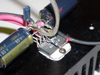
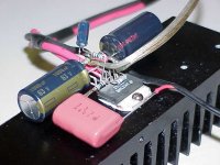
My inverted LM3875 prototype (as it sits now) is using Rubycon YXG 1000uF(63V) per +/- leg (4 total) and I hear no sluggishness or muddiness at all. In fact, my father, a long time audiophile (and aerospace engineer), was amazed at the dynamics, cleaness and musicallity of the amp with so little filter capacitance. I kept the number of parts to a minimum because I have been trying out different component brands and values on the input side. Unfortunately, a slow process, because I allow for @24 hours of a break-in period. I run the unit into dummy loads when I am not home listening to music. I have 4 more of these and plan to double them up tonight and see if there is any change. I honestly wouldn't be suprised if there wasn't any audible difference but, then again, I wouldn't consider myself to have very critical hearing either.
I have pretty much settled on a RelCap RTX 2.0uF(400V) as the input cap to use. I can hear no difference with those in the circuit or out. IOW, transparent. I don't have any other values of that brand and they are getting expensive because they might not be manufactured any more. Auricap's version sounds nice but adds coloration toward the warmer side and softens the sound just a little. I am waiting for a couple of TRT's to come in, but will probably save them for another project.
I am using Dale 2B resistors(NOS) and like them but have some Mills to try coming with the TRT cap order. My over all opinion is that there is less variation in quality of sound with changes in components in this amp than with other designs. Pretty much anything sounds good and some changes sound very good. Probably because of this IC's good design and high PSRR/CSRR, although I think Kuei talked about how using the inverted leg reacts with the ICs internal feedback. Anyway, a great bonus with this amp is that these changes are much less expensive to try than other designs.
Thanks, however...
Halojoy,
A couple of points--I don't want to use a Zobel network on the ouput if possible, and the circuit in the specification sheet has too much gain for my application. Most every general audio application circuit for these power op-amps are the same. The general principles for gain selection and proper coupling are demonstrated in all electronic devices texts and the information is also readily available on the web.
The point here in this post and I believe on this board is to apply acquired knowledge through experimentation to gain more knowledge. I apply this principle on a daily basis and in doing so I will hopefully gain better insight into the subtlties of these devices and there possible applications not only for audio but as motor drivers, etc.
By the way, the standard setup is rife with problems, not schematically, but topographically if proper design techniques are not considered when developing a PCB, if that is desired. Reading the application notes is a must.
Respectfully,
Yes, if you have proper knowledge
and test equipment
you might be able to tweak up a few 10ths of a percent
in performance
I think more of us others, who can be fooled
into doing changes we can not control
making us disappointed and frustrated
by misfires and dissasters
We have not much to lose, by playing safe
/halo - what is good for me - is not necessarary good for you
- but keep on experimenting, if you wish - who is gonna stop you?
halojoy, I was kinda suprised to hear someone in a DIY community suggesting to take the safe, easy way out..
Heh, I guess if we wanted the easy way out, we'd just buy a Gaincard and a Power Humpty (I still love that name!).
Anyhow, I think these amps are a great oppertunity to see what kind of effect different passives and different materials have on the sound of an amplifier. And as long as some degree of scientific rigor is used, even blowing something up is still worth the lesson.. Plus, these things are so cheap, its no major loss if something doesn't work. Just imagine building an Aleph-X that ends up sounding bad.. Now *that* would be "making us disappointed and frustrated."
--Jordan
Re: Yes, if you have proper knowledge
The rain (solid in your case) & the long nights gettin' you down? Perhaps bathing in some bright light will help you from being SAD.
What ever happened to "go where no man has ever gone before"?
A free man always wants to explore the edges...
In the ChipAmp we have discovered something that gives unexpected value... why not explore its limits?
dave
halojoy said:We have not much to lose, by playing safe
The rain (solid in your case) & the long nights gettin' you down? Perhaps bathing in some bright light will help you from being SAD.
What ever happened to "go where no man has ever gone before"?
A free man always wants to explore the edges...
In the ChipAmp we have discovered something that gives unexpected value... why not explore its limits?
dave
Well, you are right in most you say.
So I can not argue.
And blowing up a $10 chip or two isn't the end of the world.
Worse is if they take your $200 speakers along with them.
A nice method is to let some other experimenters do
the heavy testing.
When they finish up with something useful - that doesn't have a smell of burnt metall -
Then it is time to copy their project ....
/halo - waits until the burning is all over - then builds his amp
I re-read the Stereophile review of the Gaincard...
sparks, smoke, and fireworks from the both the first and the second units to be tested... (turned out to be a problem with the Power Humpty)
The only thing more amazing than the fact that it blew up, twice, is that the reviewer left it running for 4 weeks, even while he was away!
I guess his insurance premiums were all paid up.
It still looks like a fun project to build. You could always use it for computer speakers.
sparks, smoke, and fireworks from the both the first and the second units to be tested...
(turned out to be a problem with the Power Humpty)The only thing more amazing than the fact that it blew up, twice, is that the reviewer left it running for 4 weeks, even while he was away!
I guess his insurance premiums were all paid up.
It still looks like a fun project to build. You could always use it for computer speakers.
Yesterday I switched off my new inverted chipamp. Finally it failed to impress me.
It definitely is bass shy, bass is there and deep, but somehow too "thin" or "dry". And voices are subdued, not like a filter, more like being put to the backside. All details are there, but the overall presentation is no satisfying at least. The musical flow is there, but somehow lacklustre, hard to describe. Dynamics are a kind of exaggerated, but strangely this makes it sound less dramatic. This resembles to some tube amps, but otherwise it does not sound like tube amps at all. It tries to expand those heavy compressed music (most pop or rock music), but this does not make sense to me.
Don't get me wrong: It is a really good amplifier. But to justify all the fuss and the hype I has to be better. At the moment my other non-inverting version sound better to me.
These chip amps - to contradict somebody here - seem to be VERY much dependent on parts quality and selection, the less parts the more. How can it be that carbon resistors actually do sound better here ? And do not tell me that they are better in general.
The inverted version is definitely much more source sensitive and, although Thorsten's idea with the linear pot is good, a buffer will probably be mandatory. What about TNT's "Preamble" ?
And, I will repeat my question about the resistor (or link) from non-inverting input to ground: There is this huge difference between 220k and a link. Bias what ? And the paralled 0.1yF cap shorts AC to ground ? Maybe I did not read all the posts properly, but I did not find an explanation. Kuei ?
Klaus
ps: Yesterday I bought 32 D-size type batteries to get one of these beasts running off the mains. My "final" approach...
Lohk,
I don't know how much A-B testing you did but I think tube amps and other simple discrete SS amps show a more dramatic difference in sound when you change the caps than with this little amp. I threw 6 different types, 4 different brands of caps and 3 different input resistors in this little amp and the biggest change in sound came from using a much lower rated cap. ie from a 600V to a 100V. Which is fairly drastic but I wanted to make a meaningful change that was immediately noticable because I felt I spinning my wheels trying to alter the sound, one way or another. If you were to do that with a some other amps IMHO the change in sound would be more noticable. Yes, if you start yanking out parts, it will sound more different when you make changes. You start yanking this same percentage of parts from most other amp designs and they STOP working. Do you think this amp sounds better with metal film or carbon resistors? I bought some Caddocks for it in the beginning but was told from two different sources that they sound edgy and dry in this amp, so I am saving them for another project. As you said, this is a great amp but not worth the hype. What amp do you want to talk about? I am waiting for my AlephX boards and other parts to come in and building this one for my daughter. I recently built a DC100 that my father asked to use and I have to tell you... the Inverted GC can stand next to it very well. My 8 year old son has been eyeing my other samples hungrily and would like to build one. Not many designs out there a young boy can build with such good results. I am not saying this is the amp to rule the audio world, but if you want a simple design that sounds good and is more tolerant of different quality or less parts, then this one makes a great choice.
I don't know how much A-B testing you did but I think tube amps and other simple discrete SS amps show a more dramatic difference in sound when you change the caps than with this little amp. I threw 6 different types, 4 different brands of caps and 3 different input resistors in this little amp and the biggest change in sound came from using a much lower rated cap. ie from a 600V to a 100V. Which is fairly drastic but I wanted to make a meaningful change that was immediately noticable because I felt I spinning my wheels trying to alter the sound, one way or another. If you were to do that with a some other amps IMHO the change in sound would be more noticable. Yes, if you start yanking out parts, it will sound more different when you make changes. You start yanking this same percentage of parts from most other amp designs and they STOP working. Do you think this amp sounds better with metal film or carbon resistors? I bought some Caddocks for it in the beginning but was told from two different sources that they sound edgy and dry in this amp, so I am saving them for another project. As you said, this is a great amp but not worth the hype. What amp do you want to talk about? I am waiting for my AlephX boards and other parts to come in and building this one for my daughter. I recently built a DC100 that my father asked to use and I have to tell you... the Inverted GC can stand next to it very well. My 8 year old son has been eyeing my other samples hungrily and would like to build one. Not many designs out there a young boy can build with such good results. I am not saying this is the amp to rule the audio world, but if you want a simple design that sounds good and is more tolerant of different quality or less parts, then this one makes a great choice.
- Status
- This old topic is closed. If you want to reopen this topic, contact a moderator using the "Report Post" button.
- Home
- Amplifiers
- Chip Amps
- This is not just another gainclone