peeps,
you'll have to excuese me as this is my first amp.
I picked up a LM3875 kit (rev B PCBs) and i'm at the point where it's time to do the power on test. little scary actually, since i'm working with AC current here, and I'm less than pleased with my soldering skills (though they did improve dramatically over the course of the build)
So as mentioned i've got a LM3875 kit, an an Avel Y23 160VA 22+22V toroidial transformer. I powered the unit up, sans audio connections and I immediately started to hear the transformer crackle. it would appear that the crackling is comming from the plastic 'wrap' around the transformer, but it scared me enough to trip the power strip circuit breaker it was attached to, and double check my connections..
As far as i can tell, everything is hooked up right. The transformer started to get a little warm, so it could just be 'breaking in' but as i dont have a fuse on it (yet) i wasn't comfortable going further with my testing until I could verify that this is normal behavior.
connection wise, I'm feeding mains into a AC rated switch, from the switch to both inputs on the transformer in a parallel config. both secondaries are going into a single power supply board, wich will feed both channels.
And that's the part i'm wondering about. I assume that wiring the pimaries in parallel is fine (according to the spec sheet for the unit). The build kit isn't clear about the input section on the power supply board.. AC1/AC2 i assume is used for two seperate inputs? Can anyone shed some light on this? I'd rather not electrocute myself or burn down the house.")
you'll have to excuese me as this is my first amp.
I picked up a LM3875 kit (rev B PCBs) and i'm at the point where it's time to do the power on test. little scary actually, since i'm working with AC current here, and I'm less than pleased with my soldering skills (though they did improve dramatically over the course of the build)
So as mentioned i've got a LM3875 kit, an an Avel Y23 160VA 22+22V toroidial transformer. I powered the unit up, sans audio connections and I immediately started to hear the transformer crackle. it would appear that the crackling is comming from the plastic 'wrap' around the transformer, but it scared me enough to trip the power strip circuit breaker it was attached to, and double check my connections..
As far as i can tell, everything is hooked up right. The transformer started to get a little warm, so it could just be 'breaking in' but as i dont have a fuse on it (yet) i wasn't comfortable going further with my testing until I could verify that this is normal behavior.
connection wise, I'm feeding mains into a AC rated switch, from the switch to both inputs on the transformer in a parallel config. both secondaries are going into a single power supply board, wich will feed both channels.
And that's the part i'm wondering about. I assume that wiring the pimaries in parallel is fine (according to the spec sheet for the unit). The build kit isn't clear about the input section on the power supply board.. AC1/AC2 i assume is used for two seperate inputs? Can anyone shed some light on this? I'd rather not electrocute myself or burn down the house.
Firstly, get yourself a light bulb and wire it in series with the mains. This will protect the traffo if you have a short. Disconnect the secondaries from the PSU, and stick them in an electrical connector strip, (so there is no risk of shorting), then power up again. If the light bulb glows brightly, you have a short somewhere. If not check all voltages and make sure you have what you're expecting.
I found the problem. I had the one of the primary wires (neutral) connected to the hot lead, while the others were hooked up properly.
lucky I caught it in time methinks.
it sounds great now. even with the cheap radio-shack audio pot in the input line to deal with volume adjustment (that'll be replaced shortly) - it cuts out when I try and turn it up to full volume with my benchtop TV as the feed (rca out). can't tell yet if it's the cheap pot, or a loose connection (nothing is sodered on the output side yet, except some leads to the PCB). It's probably a combination of both.
next comes the ipod dock and the rest. i'll post pics soon.
Keyoke said:...it sounds great now. even with the cheap radio-shack audio pot in the input line to deal with volume adjustment (that'll be replaced shortly)...
BTW the "cheap radio-shack" piece says Alps on it and Made in Japan so it can't be all bad
Wire from rectifier to amp pcb
1. Okay, so I have heard about a thing that Nuuk has on Decible Dungeon somewhere about this "Light Bulb power-up test thing". All the links I have found don't point to the exact page anymore, because they moved. Anyone know where to find that article/thread?
2. Seperating amp and rectifier board? I am building P.Daniels Audio Sector LM3875, dual mono. Considering seperating the rectifier pcb from the amp pcb. They'll be on the same chassis, but with a little distance between them. I read somewhere that gounding can be an issue; but I think it makes sense, you still would bring PG+ and PG- back to starground at speaker OG right? So I would build an "embelical cord" to carry all power and ground from rectifier. Am I missing something here? That's 4 conductors between the two boards. Do I need a 5th conductor to go between PG +/- on the rectifier board and OG on the amp board, or can I simply take PG +/- on the amp board to OG for star ground?
The only part of the chassis that will be metalic or conductive is the heat-sink, so I planned to just earth to there, and then use a large bare 12 or 14 awg bare copper wire to bring grounds from speaker and power to one point, then connect that to the chassis as well.
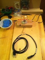
3. What kind of wire to use between amp and rectifier? The photo below shows an old computer cord I have used to make light bulb testor for power-up. Notice the lamp cord insulation melted, but the computer cord looks fine, and yes I will insulate/tape it before use. I have another computer cable, 3 conductor, stranded copper, 18awg. Would this be good or bad wire to use between rectifier and amp? I would only use the inner conductors, and build my own new sheeth with the number of conductors I need.
I also have some 19awg stranded copper Kimber TCSS that I am using for speaker signal -my instinct tells me that this is not appropriate for power wire. Is that right/wrong?
Firstly, get yourself a light bulb and wire it in series with the mains. This will protect the traffo if you have a short. Disconnect the secondaries from the PSU, and stick them in an electrical connector strip, (so there is no risk of shorting), then power up again. If the light bulb glows brightly, you have a short somewhere. If not check all voltages and make sure you have what you're expecting.
1. Okay, so I have heard about a thing that Nuuk has on Decible Dungeon somewhere about this "Light Bulb power-up test thing". All the links I have found don't point to the exact page anymore, because they moved. Anyone know where to find that article/thread?
2. Seperating amp and rectifier board? I am building P.Daniels Audio Sector LM3875, dual mono. Considering seperating the rectifier pcb from the amp pcb. They'll be on the same chassis, but with a little distance between them. I read somewhere that gounding can be an issue; but I think it makes sense, you still would bring PG+ and PG- back to starground at speaker OG right? So I would build an "embelical cord" to carry all power and ground from rectifier. Am I missing something here? That's 4 conductors between the two boards. Do I need a 5th conductor to go between PG +/- on the rectifier board and OG on the amp board, or can I simply take PG +/- on the amp board to OG for star ground?
The only part of the chassis that will be metalic or conductive is the heat-sink, so I planned to just earth to there, and then use a large bare 12 or 14 awg bare copper wire to bring grounds from speaker and power to one point, then connect that to the chassis as well.
3. What kind of wire to use between amp and rectifier? The photo below shows an old computer cord I have used to make light bulb testor for power-up. Notice the lamp cord insulation melted, but the computer cord looks fine, and yes I will insulate/tape it before use. I have another computer cable, 3 conductor, stranded copper, 18awg. Would this be good or bad wire to use between rectifier and amp? I would only use the inner conductors, and build my own new sheeth with the number of conductors I need.
I also have some 19awg stranded copper Kimber TCSS that I am using for speaker signal -my instinct tells me that this is not appropriate for power wire. Is that right/wrong?
Attachments
1. I can't find it either.
2.If I understand correctly the 4 wires would do it. As far as I recall, the speaker out negative comes right off the amplifier board.
3. The 18awg conductors will work. They are likely 300v or 600v rated wire.
If the Kimber 19awg is speaker wire, the insulation won't have a high enough voltage rating, if any at all. It would "work", but is not a good habit to get into.
Generally you want all the wire to be rated higher then the highest voltage seen, regardless of the voltage it carries. In the case of a typical chipamp, the highest voltage in the amp would be the 120VAC, so 300v wire would due.
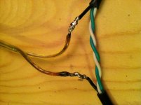
The burnt speaker wire in your bulb tester is a good example. You can see how quickly the insulation broke down with heat vs the computer cable. It will "work" but is not ideal from a safety point of view.
2.If I understand correctly the 4 wires would do it. As far as I recall, the speaker out negative comes right off the amplifier board.
3. The 18awg conductors will work. They are likely 300v or 600v rated wire.
If the Kimber 19awg is speaker wire, the insulation won't have a high enough voltage rating, if any at all. It would "work", but is not a good habit to get into.
Generally you want all the wire to be rated higher then the highest voltage seen, regardless of the voltage it carries. In the case of a typical chipamp, the highest voltage in the amp would be the 120VAC, so 300v wire would due.
The burnt speaker wire in your bulb tester is a good example. You can see how quickly the insulation broke down with heat vs the computer cable. It will "work" but is not ideal from a safety point of view.
.....
3. The 18awg conductors will work. They are likely 300v or 600v rated wire.
.......
Generally you want all the wire to be rated higher then the highest voltage seen, regardless of the voltage it carries. In the case of a typical chipamp, the highest voltage in the amp would be the 120VAC, so 300v wire would due.
...............
Thanks for fielding my questions GloBug.
The lamp-cord you saw that melted was literally cut off an old broken desk-lamp, and is not the Kimber I was reffering to. The Kimber is called "hookup wire",.. whatever that means. I will be use it only for between the pcb and speaker-binding posts. It seems very sturdy,... not super flexable, but it is awfully small, and yes I see now that the insulation is very thin.
So that makes sense about the voltage rating. Would a solid core wire have benefit over stranded core for that 4-conducter line between the rectifier and amp?
Tomorrow I will place one last order for the two transformers. I could easily add some wire to my order if it would be superior to the old computer power cord I have.
What is the wire I saw on the photo of your LM3875 GloBug? The orange wire looks heavy-duty.

If the Kimber is "hookup" wire, you should be good to go.
I prefer solid core for most internal connections, where practical.
It does a neater, more rigid job too IMO, you don't have to secure it as much.
Lengths longer then 4" or 5" could benefit from stranded connections though, if you have it.
The orange wire is an automotive type fuse, 12awg or so.
The rest is 18awg? stranded Beldin wire I use for flexible leads, bread boards and speaker wire etc. It is 4 conductor + shielded cable normally.
The forth conductor is uninsulated so I only get red, black and clear when I separate it.
Some would prefer a stranded wire in high current situations, but is not always needed if you use big enough solid core.
If you want to order some new wire is up to you, I use both sometimes depending on the need and the colour and voltage etc.
It is nice to have multiple colours of the same type of wire, for identification, although it's more of a luxury than anything else.
- Status
- This old topic is closed. If you want to reopen this topic, contact a moderator using the "Report Post" button.
- Home
- Amplifiers
- Chip Amps
- LM3875 power up test.. and it crackles w/o speakers attached?