hi,
i´m having the following problem with my circuit using the lm 3886:
if the speaker is connected to the output of the amp, it plays for 3 or 4 secs after power up and then it stops, the current sinks to about 20 mA and then nothing changes until a new power up. my circuit is nearly the application circuit from the datasheet.
a few more infos on my circuit:
-power supply ist quite low at the moment, +- 15V
-blocking capacitors are soldered dirctly to the pins of the chip.
-there are two 1000uF bypass caps on the chip board
-the mute pin (pin 8) ist connected to Vs- over a 22k resistor, so mute mode should be off
i know that for a detailed analysis i had to give more infos, but i was
hoping that this is perhaps a "standard" problem with well known reasons.
thank in advance,
jonas
yes, the chip is mounted upon a heatsink. it should be big enough at least for testing, its about 12X7X3 cm.
ive measured the voltage drop over the resistor which connects the mute pin to gnd. it decreases continuously after power up, until the chip is in mute mode. the decrease is much faster when a speaker is connected, but also with open output the chip goes tu mute mode, after a few minutes
ive measured the voltage drop over the resistor which connects the mute pin to gnd. it decreases continuously after power up, until the chip is in mute mode. the decrease is much faster when a speaker is connected, but also with open output the chip goes tu mute mode, after a few minutes
ok, that solved it! with about 25 VDC the problem described above has
vanished. but here´s the next:
without input signal(input is open), the dc voltage across the output is about 9V without speaker. when connecting an 8ohm speaker, it rises to 10V. that means the current drawn is more than 1 amp.
accordingly the chip gets quite hot...
what could be the reason?
thx for every answer!
vanished. but here´s the next:
without input signal(input is open), the dc voltage across the output is about 9V without speaker. when connecting an 8ohm speaker, it rises to 10V. that means the current drawn is more than 1 amp
.accordingly the chip gets quite hot...
what could be the reason?
thx for every answer!
I bet your first problem was the Mute resistor was too high. Change it to 15K for the 15V. The good way to remember what value to use is to simply take the supply voltage and put a K on it. So if +/-25V then use something around 25K, round down to a standard value. Having more current pulled out of the Mute pin will not hurt anything.
If getting DC then something is wrong with the circuit. Check to be sure you are not getting DC from the input, is there an input cap? If not is there any DC from the source? Check the caps. in the circuit as the most likely problem.
-SL
If getting DC then something is wrong with the circuit. Check to be sure you are not getting DC from the input, is there an input cap? If not is there any DC from the source? Check the caps. in the circuit as the most likely problem.
-SL
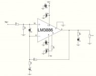
thx for the answers. i changed something in the circuit, now it´s already better. here´s the circuit diagram i´m using right now. i still have 1.33 V of DC at the output. ive measured the dc voltage of the source(a notebook), and my multimeter says 2,51V! so how to get rid of this DC voltage?
i replaced the resistor R7 in the diagram by one with 1k, that worked. but this decreases the ipnut resistance severely and perhaps(i dont know) has some other disadavantages. then i used a 4700uF coupling cap and the dc voltage decreased to 80mV. so is that the way to do it, or is there another way?
i think a smaller coupling cap should reduce it further. what is the effect of the capacitiy of this cap, i.e. how does it influence the sound?
Attachments
1k resistor will make it hard for the source component.
Have you tried put the 22k resistor with the 4700uf decoupling caps?
Change R6 to 10k,R4 to 2.7ohms
Check the decoupling caps(according to the schematic,a cap is reversed
You can put a film cap in the input
But the first thing is to check amp with another source component,least to make sure the amp is working properly
If you measure a DC voltage at the output of the source then you MUST use an input coupling capacitor to block that DC voltage. This is the easiest solution. Put R7 back to 22k ohms. Then add an input capacitor of value 1uf or higher. The only advantage to go higher is to get more low bass response but with 22K and 1uF then you will have a -3dB point of ~7Hz. Plenty low. Or you can increase R7 to 33K - 47K to lower the -3dB point. Look at the LM4780 datasheet (dual LM3886) and there is several schematics in there showing an input capacitor. The demo board schematic is on page 21. Make these changes and you should not have any problems. Reduce the Mute resistor to about 12K- 15K and you will be fine with +/-15V supply. I have run from +/-15V without any problems.
Check all other capacitors to be sure they are correct. 80mV is not great but is also not bad, enough that your speakers will be fine.
-SL
Check all other capacitors to be sure they are correct. 80mV is not great but is also not bad, enough that your speakers will be fine.
-SL
the decoupling cap was reversed only in the circuit diagram, sorry for that...
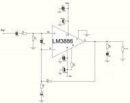
ok, now i changed it in the following way: i added a coupling cap (i chose the value because i had a bipolar cap with 2.2uF) .
now, with the source open, the dc voltage ist 40mV. with the source connected, it is 0mV. its getting better!
i still have a few questions:
- do i need the 1k resistor in series with the coupling cap, what is it good for?
- if i want to use a potentiometer for volume control, where should i put it: in front or behind the coupling cap, or doesnt it matter at all?
Attachments
1k resistor at + input http://www.national.com/ds/LM/LM3886.pdf page 8
potentiometer placement (capacitor before potentiometer) check datasheet page1
potentiometer placement (capacitor before potentiometer) check datasheet page1
Glad things are working out. Don't worry about beginner questions, we are all beginners relative to someone else. As long as you are willing to do some work and learn I don't think people mind helping at all. It is those who want to be spoon fed that drive people crazy.
-SL
-SL
i tried it with an ipod, there were no problems at all. and now with the coupling cap it works also fine with the notebook as source.
the reference to the datasheet is very well for me, if i don´t understand it there i can ask again.
but in this case i found the answers there.
i will post pictures as soon as a have finished the amp, but it will take a while, for i have to work on the chassis yet, which is completely self-made.
jonas
- Status
- This old topic is closed. If you want to reopen this topic, contact a moderator using the "Report Post" button.
- Home
- Amplifiers
- Chip Amps
- problem with lm 3886 application circuit