Not all amps need to be square boxes, do they? This LM3886 kit has been waiting for an enclosure for ages. Now it has one. Wood, leather, brass etc.
GORGEOUS AMPS! I cannot believe the quality of workmanship, and design that you and others have in your projects! These are the quality and innovativeness I can only dream of.
The case is a 2U Dissipante from ModuShop. I sent the panels to Schaeffer for drilling and legends.WOW! That looks awesome! Where dod you get the case, or did you scratch build that too?
GORGEOUS AMPS! I cannot believe the quality of workmanship, and design that you and others have in your projects! These are the quality and innovativeness I can only dream of.
Thanks a lot! Much appreciated. I find designing and building this stuff very therapeutic. I'm not much of an electrical designer, but I like to design and create all sorts of stuff. There's so much great stuff being built by the DIY Audio community it's easy to spend hours just looking at all the stuff you can find here. In fact the gainclone just got a new best friend which can be seen in the tube section gallery...
Thanks Jem. It was certainly a challenge trying to get it all crammed in and still allow for airflow. The BT board connector wires seemed to be made of angel's hair - so thin they pretty much broke off the pot by simply looking at them!
This amp sounds decent enough for about maybe up to around the first third of the power. It then starts to sound a bit muffled or constrained before moving into a higher distortion band close to max output.
It is louder and has a clearer tone than the JLH but the JLH is definitely a richer, smoother sounding amp. The JLH I feel is suited to 'easy listening/chill out' whereas this one is happy with pop radio type music. I found high range female vocals a little on the annoying side though.
This one I feel is quite acceptable for a desktop near field environment where you don't need to crank it. It also takes up less space and generates much less heat than the JLH.
The amp is rated 25w into 4 ohm but so far I've only got it to my 'level 2' sacrificial workshop speakers - 50w 8 ohm JVCs. Maybe it'll sound better on some 4ohm..?
Hello avtech,
Many thanks for your response and for your very good descriptions.
I was thinking about making a 2050, but then remembered after reading your words that I'd got a couple of 3886's somewhere and then found them.
I've got a 'fat sound' GC with a largish power supply and a defunct one with a pair of toroids in it. I also remembered Mick Feuerbacher's minimalist 3886 and I'm going to see what that's like.
Cheers - Jem
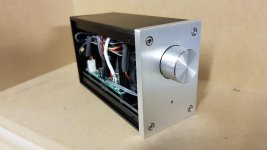
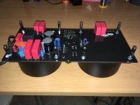
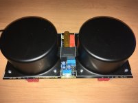
A pair of TDA2050 kits and a Bluetooth receiver squeezed into the smallest case I could manage.
Mostly assembly and figuring out how to mount everything but still an enjoyable side project")
Bluetooth is the only input?
Hello all,
I used Mick Feuerbacher's two resistor circuit.
I wanted to make the simplest and least expensive chip amp I could.
A wooden box. Two transformers second hand on Ebay, bought some years ago.
Junk box items; mains socket, 4 bridge rectifiers, old very robust DP switch, heatsinks from a scrap yard, connectors and single core wire.
And I bought for £16.74 resistors and capacitors from Cricklewood Electronics
I thought it's going to hum with no screened cables, it doesn't
I thought there would be some RF interference, there is none.
In fact it's the best amp I've ever made, sonically superb.
Cheers
I used Mick Feuerbacher's two resistor circuit.
I wanted to make the simplest and least expensive chip amp I could.
A wooden box. Two transformers second hand on Ebay, bought some years ago.
Junk box items; mains socket, 4 bridge rectifiers, old very robust DP switch, heatsinks from a scrap yard, connectors and single core wire.
And I bought for £16.74 resistors and capacitors from Cricklewood Electronics
An externally hosted image should be here but it was not working when we last tested it.
I thought it's going to hum with no screened cables, it doesn't
I thought there would be some RF interference, there is none.
In fact it's the best amp I've ever made, sonically superb.
Cheers
Bluetooth is the only input?
Apologies, I didn't get a notification this time.
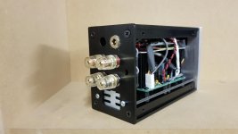
Yes, at this stage I am only using a bluetooth input but I have a hole ready to accept a 3.5mm jack (just need to buy the jack).
The bluetooth module has a function whereby it detects an additional input source and it will pass-thru the signal.
LM386 Bench Speaker
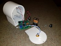
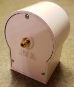
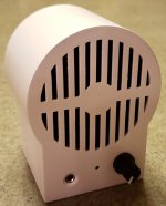
With a whopping output of about 500mW max, this little LM386 amplified speaker departs a bit from most of the creations posted here. The case components were modeled in SolidWorks and were printed with PLA on a Monoprice Select Mini 3D printer.
More info is here: LM386 Amplifier For The Bench – crosstimbers audio
Attachments
With a whopping output of about 500mW max, this little LM386 amplified speaker departs a bit from most of the creations posted here. The case components were modeled in SolidWorks and were printed with PLA on a Monoprice Select Mini 3D printer.
More info is here: LM386 Amplifier For The Bench – crosstimbers audio
Nice to see something different.
What are your thoughts on the 3d printer? Your end result looks pretty good.
Nice to see something different.
What are your thoughts on the 3d printer? Your end result looks pretty good.
Thanks. The 3D printed case took a couple of coats of filler primer, some filler putty, and some sanding to smooth it to the point where I got tired of messing with it. The paint is 2 coats of Krylon Gloss White Enamel.
My experience with the Monoprice printer has been mostly positive. The SD card reader has stopped working so I have it connected to my computer via USB, which works so far. I do, however, find the available build volume of the Mini to be constraining.
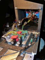
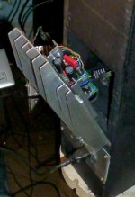
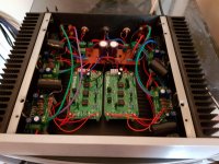
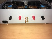
KMTech 24dB/octave crossovers and gainclone boards, powered from a +/-35V supply in a separate box. Gives a very acceptable near field sound from a pair of Tannoy 607s run active.
Wiring is a bit "prototype" for now, while the roundtuits are accumulated.
Wiring is a bit "prototype" for now, while the roundtuits are accumulated.
Attachments
My man!
Absolutely a wonderful little project, something one should try at least a few times in a lifetime as a father/son project or I don't know, to make your friends happy by giving them a gift that you made with your own hands.
With a whopping output of about 500mW max, this little LM386 amplified speaker ...
Absolutely a wonderful little project, something one should try at least a few times in a lifetime as a father/son project or I don't know, to make your friends happy by giving them a gift that you made with your own hands.
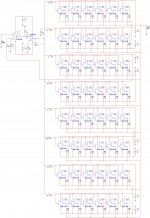
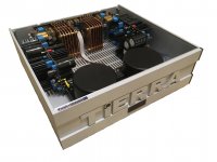
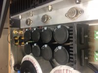
My new Amp
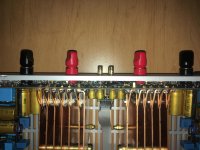
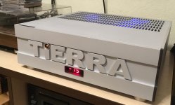
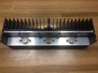
30 W/4 Ohm, 15 W/8 Ohm
SR 400 V/usec
0 Hz - 8 MHz (can amplify video signal)
Output R: 0.0001 Ohm
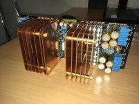
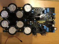
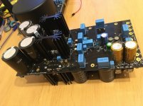
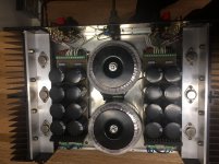
400 W full stable power supply +/- 18 V. About 1 Farad inside.
48 BUF634T in each channel (parallel connection).
30 W/4 Ohm, 15 W/8 Ohm
SR 400 V/usec
0 Hz - 8 MHz (can amplify video signal
)Output R: 0.0001 Ohm
400 W full stable power supply +/- 18 V. About 1 Farad inside.
48 BUF634T in each channel (parallel connection).
Attachments
-
 Tierra.jpg562.3 KB · Views: 669
 -
 IMG_1648.jpg269.2 KB · Views: 609
 -
 IMG_0950.jpg262.5 KB · Views: 562
 -
 IMG_0948.jpg246.8 KB · Views: 576
 -
 IMG_0832.jpg215.1 KB · Views: 549
 -
 IMG_0833.jpg166.7 KB · Views: 514
 -
 IMG_1791.jpg420.4 KB · Views: 639
 -
 Inside.jpg360.7 KB · Views: 867
 -
 IMG_1790.jpg938.6 KB · Views: 591
 -
 IMG_1688r.jpg580.5 KB · Views: 561
Last edited:
make itNot all amps need to be square boxes, do they? This LM3886 kit has been waiting for an enclosure for ages. Now it has one. Wood, leather, brass etc.
Its work of art!!
have you made any step by step videos to show how to make it?
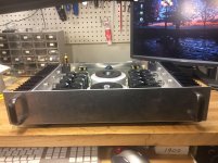
Recent amp project with Apex PA07
Here’s my recent amp project based on the Apex Microtechnology PA07 hybrid operational amplifier. I haven’t seen Apex opamps used here before, so I thought it might of interest to the group. The PA07 is a power opamp with a FET input that runs in Class A/B mode off a +/- 50V supply with a peak output current of +/- 5A. It comes in a metal 8-pin TO-3 package. It’s suitable of audio amps in the 60W range. I know these chips are kind of pricey but I got mine from a surplus house many years ago for next to nothing.
My amp is a dual three-channel configuration - six channels total at about 70W per. My speakers are 2-way with two woofers and one tweeter per cabinet, so the idea was to go with an active crossover and a dedicated amp for each driver, and so the need for six channels.
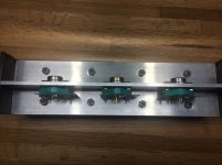
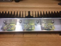
The external circuitry was kept to an absolute minimum. Since the PA07 is internally compensated, thermally protected, and protected against inductive kickback only seven external components were needed. These are the gain control resistors, power supply decoupling caps and current limiting resistors. All are SMD and fit on a small 30x50 mm board which is built around a socket for the 8-pin TO-3.
I omitted the traditional input coupling capacitor since these are present at the output of the active crossover anyway. In prototyping the PA07 exhibited virtually no power-on transient or pop-noise, so I decided a mute circuit was not needed.
I have been listening to this for a couple of weeks now and I have to say the sound is truly amazing….. warm, clean, powerful, and detailed. Everything you want an amp to be. I don’t have the equipment to measure THD so I can’t provide any numbers in this department, but quite frankly, I don’t care. I’ve been listening to and building amps for 40+ years and this thing is up there with the best of the best. It’s hard to say how much is attributable to the amp itself, or the transition to bi-amping with an active crossover, or the dedicated amp-per-driver technique, but the combination of those has been a really nice improvement and well worth it.
p { margin-bottom: 0.1in; direction: ltr; color: rgb(0, 0, 10); line-height: 120%; text-align: left; }p.western { font-family: "Cambria", serif; font-size: 12pt; }p.cjk { font-family: "MS 明朝"; font-size: 12pt; }p.ctl { font-size: 12pt; }
Here’s my recent amp project based on the Apex Microtechnology PA07 hybrid operational amplifier. I haven’t seen Apex opamps used here before, so I thought it might of interest to the group. The PA07 is a power opamp with a FET input that runs in Class A/B mode off a +/- 50V supply with a peak output current of +/- 5A. It comes in a metal 8-pin TO-3 package. It’s suitable of audio amps in the 60W range. I know these chips are kind of pricey but I got mine from a surplus house many years ago for next to nothing.
My amp is a dual three-channel configuration - six channels total at about 70W per. My speakers are 2-way with two woofers and one tweeter per cabinet, so the idea was to go with an active crossover and a dedicated amp for each driver, and so the need for six channels.
The external circuitry was kept to an absolute minimum. Since the PA07 is internally compensated, thermally protected, and protected against inductive kickback only seven external components were needed. These are the gain control resistors, power supply decoupling caps and current limiting resistors. All are SMD and fit on a small 30x50 mm board which is built around a socket for the 8-pin TO-3.
I omitted the traditional input coupling capacitor since these are present at the output of the active crossover anyway. In prototyping the PA07 exhibited virtually no power-on transient or pop-noise, so I decided a mute circuit was not needed.
I have been listening to this for a couple of weeks now and I have to say the sound is truly amazing….. warm, clean, powerful, and detailed. Everything you want an amp to be. I don’t have the equipment to measure THD so I can’t provide any numbers in this department, but quite frankly, I don’t care. I’ve been listening to and building amps for 40+ years and this thing is up there with the best of the best. It’s hard to say how much is attributable to the amp itself, or the transition to bi-amping with an active crossover, or the dedicated amp-per-driver technique, but the combination of those has been a really nice improvement and well worth it.
p { margin-bottom: 0.1in; direction: ltr; color: rgb(0, 0, 10); line-height: 120%; text-align: left; }p.western { font-family: "Cambria", serif; font-size: 12pt; }p.cjk { font-family: "MS 明朝"; font-size: 12pt; }p.ctl { font-size: 12pt; }
Attachments
- Home
- Amplifiers
- Chip Amps
- Chip Amp Photo Gallery