
This amp is for my pc, and i use my sound card for bass-cut. The main speakers dont actually get any bass from below about 120 hz.
So the enclosure size isnt a problem really. And they needed to be as small as possible because they need to fit on my desk hehe.
The pots arent motorized, its just a kinda of a preset thing.
I set it at after a bit of experimenting with the computer sound contrl.
So the enclosure size isnt a problem really. And they needed to be as small as possible because they need to fit on my desk hehe.
The pots arent motorized, its just a kinda of a preset thing.
I set it at after a bit of experimenting with the computer sound contrl.
Thanks ttan98
Sasmit, the fans are temperature controlled via a sensor on the sub amp module heatsink. They run at a nominal voltage of around 3.3 volts where they are barely audible. As the heatsink warms up, the fans speed up.
I am not worried about the LM3875 modules, as they have their own temperature control and protection systems.
Rainwulf said:Thanks ttan98
Sasmit, the fans are temperature controlled via a sensor on the sub amp module heatsink. They run at a nominal voltage of around 3.3 volts where they are barely audible. As the heatsink warms up, the fans speed up.
I am not worried about the LM3875 modules, as they have their own temperature control and protection systems.
you are welcome to put the circuit that controls the fan speed here.
Folks,
I completed the MyRef RevC from the recent group buy.
The chassis has a spartan, industrial look, and everything is made easy
to remove. I mounted the PCBs on a "mezzanine" card of bakelite.
The shaft coupler is the brass insert from a 60A electrical connector.
The front bushing for the shaft was scavenged from a cheap rotary switch.
The power switch contacts have 1KV rated caps across them.
No turn-on or turn-off thump at all, and the amp is dead quiet. DC offset is like 5mV.
Some things like the cheesy LED holder and the knob will be replaced once I
have better ones.
The build pics are here -
http://picasaweb.google.com/prasadb/MauroMyRefRevC#
Thanks for looking
Prasad
Attachments
These are the diagrams of the power supply and timer and associated relays, as well as the fan controller.
The caps on the transistor bases are 22uf.
The resistors are 47k.
Gives around a 1.5 second delay between each segment.
When power is plugged into the IEC plug at the back, the 12 volt toroid is immediately powered on. It provides voltage to the first 3 pin 7812 regulator, and thats where it stops.
When the main switch is turned on, it earths out the primary relay, turning it on, then supplying current to the rest of the timer circuits in turn.
The switched phono plug goes to a relay inside my PC. Its powered up when the PC is running. If the pc turns off, the relay turns off, which breaks the earth to the primary relay, thus turning the entire amp off instantly.
As each segment charges and turns on its relay, the stages progress.
The first stage is just a simple turn on delay. It does nothing other then to give a second before the sequence starts. This allows for loose power cable or something.
After the first second, the second stage turns on. This provides an earth to the first 240ac rated relay. This relay allows 240 volts to the main amp transformers through the Rl on the second relay. This is the "soft" turn on feature.
In my amp, Rl is two 33ohm resistors in parallel. This allows a small amount of current to rush to the main toroids, which charge up the main caps slowly.
After another second, the third stage activates, shorting out RL, and allowing full 240 volts to the main toroids. The amp itself is now powered up and stabilising.
The speaker relays are still disconnected at the moment, the speakers see a dead short, and the amp modules see an open circuit. This allows the amps to stablise.
Once the last stage triggers, the speaker relays are all activated by current from the 7812 reg, connecting the speakers to the amp outputs. The amp is now fully activated and running. The last 7812 supplies 12 volts to the fan controller, which also turns on at the last stage.
12 volts DC from output of the first regulator is also wired to an led in the power switch. This shows that the amp has power. Even if the amp is in standby, with the computer off, this LED is on, so i know its ready to go.
That wiring is not shown.
The switched phono plug is one of those ones that short circuit internally if you unplug the connector. That way if i want to run the amp separately, all i have to do is pull out the plug.
Main Amp psu.
4 toroids in total, one is the standby and timer operator.
Its running as soon as you plug power in.
The rest are the main amp supplies, and wont turn on until the timer circuit allows them too.
The secondaries are separately rectified and then fed to the banks of the main power caps.
Not very well shown is that the main supplies are all star earthed to a copper bar 2 by 4mm across at the bottom of the amp.
The timer circuit is NOT EARTHED to this point. Its floating. This prevents any switching noise from getting into the main supplies. Its why i use relays. Total isolation.
There is NO electrical connection between the timer circuit and relays to the main power supplies.
The fan controller.
Very cheap and simple. A 5 volt regulator is "boosted" by putting a ptc thermistor on its earth side.
A PTC thermister is normally very low resistance. 100 ohms or less. This effectively means the 7805 puts out around 5.5 volts. Thats dropped across the two diodes to around 4, which means the fans run very slowly.
The start cap across the diodes is optional, some fans may need it though. On first start, this cap is a short, thus putting the 5.5 volts across the fans. This gives them a kick, then as it charges, the voltage drops to the normal level.
I dont have it in my circuit, my fans have no problems starting at this low voltage.
When the PTC heats up ( its mounted on the subwoofer amp module) the 5 volt regulator slowly raises its output voltage to maintain around 5 volts between its earth and output pin. So it can continue to raise until it hits the top of 12 volts, where the 5 volt reg puts out around 10.5 volts. This is dropped to about 9 volts because of the diodes, and the fans run much faster.
The speaker relay protection.
Simple. Both speaker pins are at earth when the relays have no power. This is system earth. The amp active out is isolated open circuit.
When the timer activates and provides the 12 volts through its 12 volt regulator, the relays pull in, and route the amp output to the active line on the speakers.
All this has been designed to prevent surges on turn on, thumps in the speakers, and just to prevent basic overloads.
It also has a measure of protection to sporadic outages at the 240 line, or the slave relay. If there is a loose connection, the amp doesnt power up and down multiple times a second and possibly blow a fuse.
The first stage of the timer circuit drops out as soon as it loses power either due to an outage, or the slave line faults, and the whole amp powers down, and wont power up until the first timer stage triggers after a second.
The 240 volt relays are rated at 10 amps.
The speaker relays are all high current, with 30 amps on the normally closed contacts, and 40 amps on the normally open ones.
This means that the amp outputs are going through the contacts rated at 40 amps.
An externally hosted image should be here but it was not working when we last tested it.
The caps on the transistor bases are 22uf.
The resistors are 47k.
Gives around a 1.5 second delay between each segment.
When power is plugged into the IEC plug at the back, the 12 volt toroid is immediately powered on. It provides voltage to the first 3 pin 7812 regulator, and thats where it stops.
When the main switch is turned on, it earths out the primary relay, turning it on, then supplying current to the rest of the timer circuits in turn.
The switched phono plug goes to a relay inside my PC. Its powered up when the PC is running. If the pc turns off, the relay turns off, which breaks the earth to the primary relay, thus turning the entire amp off instantly.
As each segment charges and turns on its relay, the stages progress.
The first stage is just a simple turn on delay. It does nothing other then to give a second before the sequence starts. This allows for loose power cable or something.
After the first second, the second stage turns on. This provides an earth to the first 240ac rated relay. This relay allows 240 volts to the main amp transformers through the Rl on the second relay. This is the "soft" turn on feature.
In my amp, Rl is two 33ohm resistors in parallel. This allows a small amount of current to rush to the main toroids, which charge up the main caps slowly.
After another second, the third stage activates, shorting out RL, and allowing full 240 volts to the main toroids. The amp itself is now powered up and stabilising.
The speaker relays are still disconnected at the moment, the speakers see a dead short, and the amp modules see an open circuit. This allows the amps to stablise.
Once the last stage triggers, the speaker relays are all activated by current from the 7812 reg, connecting the speakers to the amp outputs. The amp is now fully activated and running. The last 7812 supplies 12 volts to the fan controller, which also turns on at the last stage.
12 volts DC from output of the first regulator is also wired to an led in the power switch. This shows that the amp has power. Even if the amp is in standby, with the computer off, this LED is on, so i know its ready to go.
That wiring is not shown.
The switched phono plug is one of those ones that short circuit internally if you unplug the connector. That way if i want to run the amp separately, all i have to do is pull out the plug.
An externally hosted image should be here but it was not working when we last tested it.
Main Amp psu.
4 toroids in total, one is the standby and timer operator.
Its running as soon as you plug power in.
The rest are the main amp supplies, and wont turn on until the timer circuit allows them too.
The secondaries are separately rectified and then fed to the banks of the main power caps.
Not very well shown is that the main supplies are all star earthed to a copper bar 2 by 4mm across at the bottom of the amp.
The timer circuit is NOT EARTHED to this point. Its floating. This prevents any switching noise from getting into the main supplies. Its why i use relays. Total isolation.
There is NO electrical connection between the timer circuit and relays to the main power supplies.
An externally hosted image should be here but it was not working when we last tested it.
The fan controller.
Very cheap and simple. A 5 volt regulator is "boosted" by putting a ptc thermistor on its earth side.
A PTC thermister is normally very low resistance. 100 ohms or less. This effectively means the 7805 puts out around 5.5 volts. Thats dropped across the two diodes to around 4, which means the fans run very slowly.
The start cap across the diodes is optional, some fans may need it though. On first start, this cap is a short, thus putting the 5.5 volts across the fans. This gives them a kick, then as it charges, the voltage drops to the normal level.
I dont have it in my circuit, my fans have no problems starting at this low voltage.
When the PTC heats up ( its mounted on the subwoofer amp module) the 5 volt regulator slowly raises its output voltage to maintain around 5 volts between its earth and output pin. So it can continue to raise until it hits the top of 12 volts, where the 5 volt reg puts out around 10.5 volts. This is dropped to about 9 volts because of the diodes, and the fans run much faster.
An externally hosted image should be here but it was not working when we last tested it.
The speaker relay protection.
Simple. Both speaker pins are at earth when the relays have no power. This is system earth. The amp active out is isolated open circuit.
When the timer activates and provides the 12 volts through its 12 volt regulator, the relays pull in, and route the amp output to the active line on the speakers.
All this has been designed to prevent surges on turn on, thumps in the speakers, and just to prevent basic overloads.
It also has a measure of protection to sporadic outages at the 240 line, or the slave relay. If there is a loose connection, the amp doesnt power up and down multiple times a second and possibly blow a fuse.
The first stage of the timer circuit drops out as soon as it loses power either due to an outage, or the slave line faults, and the whole amp powers down, and wont power up until the first timer stage triggers after a second.
The 240 volt relays are rated at 10 amps.
The speaker relays are all high current, with 30 amps on the normally closed contacts, and 40 amps on the normally open ones.
This means that the amp outputs are going through the contacts rated at 40 amps.
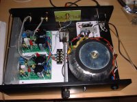
Bi-amp case project-myRef+TDA7294
A few pics of my 'assembly project' for the biamp I'm using to drive my new Fonken167s with woofers/subs in the base.
Chassis was recycled from dead CD player. Cherry faceplate and knobs, paua dot markers.
Controls: (L to R) Power, Full-range volume, 'Master volume', Balance, Input select.
A pair of myref 3886 amps drive the Fostex167s.
An eBay TDA7294 amp does woofer duty with signal via a low-pass (~300Hz) filter.
Cheers
John
A few pics of my 'assembly project' for the biamp I'm using to drive my new Fonken167s with woofers/subs in the base.
An externally hosted image should be here but it was not working when we last tested it.
Chassis was recycled from dead CD player. Cherry faceplate and knobs, paua dot markers.
An externally hosted image should be here but it was not working when we last tested it.
Controls: (L to R) Power, Full-range volume, 'Master volume', Balance, Input select.
An externally hosted image should be here but it was not working when we last tested it.
Amps:
A pair of myref 3886 amps drive the Fostex167s.
An eBay TDA7294 amp does woofer duty with signal via a low-pass (~300Hz) filter.
An externally hosted image should be here but it was not working when we last tested it.
Cheers
John
My LM3886 stereo amplifier (Mauro shematic):
An externally hosted image should be here but it was not working when we last tested it.
An externally hosted image should be here but it was not working when we last tested it.
An externally hosted image should be here but it was not working when we last tested it.
An externally hosted image should be here but it was not working when we last tested it.
- Home
- Amplifiers
- Chip Amps
- Chip Amp Photo Gallery