


Hi,
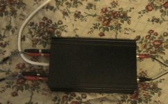
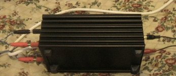
the walls of the diecast case are 2 mm. I am not absolutely sure about the heatsinking. It is running now since about two weeks (I never switch it off) and even when I play it loud, the case never gets more than handwarm (say 40°C at the position of the chips). I was however a little surprised that the whole top of the case is always about 35 °C or so, even if I dont play music.
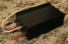
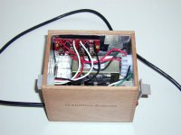
Therefore I tought about adding two little heatsinks (black finned thingies about 4 x 4 cm) on the outside of the case and fix them with the same screws as the chips (seen on the last image).
I will post images if I make this change.
Mick
the walls of the diecast case are 2 mm. I am not absolutely sure about the heatsinking. It is running now since about two weeks (I never switch it off) and even when I play it loud, the case never gets more than handwarm (say 40°C at the position of the chips). I was however a little surprised that the whole top of the case is always about 35 °C or so, even if I dont play music.
Therefore I tought about adding two little heatsinks (black finned thingies about 4 x 4 cm) on the outside of the case and fix them with the same screws as the chips (seen on the last image).
I will post images if I make this change.
Mick
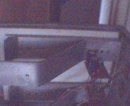
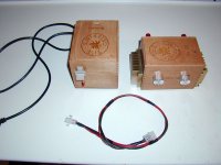
Its basically just the datasheet schematic for a 2 channel bridged amp useing a single TDA1554Q except it uses 1uF input capacitors.. Case was bought on Ebay, Actually have two of them and they are stackable so i might make a preamp or another amp in the other one and stack them.. mabey for bi-amping my system..
Attachments
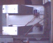
power supply is a ~100Va toroid i found in my box of bits, It has two 6.5V secondarries, gives me about 19V after rectification.. smoothing is a single 4700uF electrolytic bypassed with a 1uF something else (not sure.. bought them on ebay.. same i use for the input caps.. work nicley.. little blue things)
Attachments
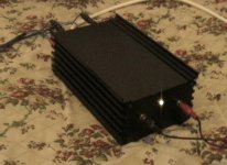
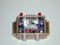
Some of the more observant of you might notice it is still missing a standby switch (there actually was one but i managed to break it  ) under the Led..
Still, I'm happy with it, more than loud enough, some of you might also notice that there is no volume control.. this is because i run it either from my computer or from my mixing desk depending what i'm useing it for at the time.. Sound pretty good aswell, better than any of my comercial amps..
Thanks for looking,
Owen
) under the Led.. Still, I'm happy with it, more than loud enough, some of you might also notice that there is no volume control.. this is because i run it either from my computer or from my mixing desk depending what i'm useing it for at the time.. Sound pretty good aswell, better than any of my comercial amps..
Thanks for looking,
Owen
Attachments
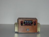
Industrial Gainclone:
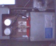
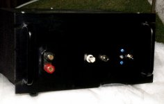
I built one to test speakers -- you only need a couple of watts -- the case was discarded when they upgraded the music system in our parish -- nice beefy transformer with 2 24,000uF caps -- I used star grounds throughout, polypropylene snubber across the diode bridge, insulated BNC connector with a post to which I attach the signal source's chassis ground. the two blue "superbright" LED's are connected to the respective power supply rails and bleed down the power supply capacitors at around 20 milliamps. distortion at 1kHz is around 0.007% which is decent for an LM3875:
I built one to test speakers -- you only need a couple of watts -- the case was discarded when they upgraded the music system in our parish -- nice beefy transformer with 2 24,000uF caps -- I used star grounds throughout, polypropylene snubber across the diode bridge, insulated BNC connector with a post to which I attach the signal source's chassis ground. the two blue "superbright" LED's are connected to the respective power supply rails and bleed down the power supply capacitors at around 20 milliamps. distortion at 1kHz is around 0.007% which is decent for an LM3875:
Attachments
troystg said:"upgraded the music system in our parish"
Church or state?
In the People's Republic of New Jersey we have towns and villages and a tax-collector as feared as that of any French nobleman.
St. Rose -- a Catholic Church which tried to pretend it was High Church U.K. style until the "new people" moved in. New people refers to those like me, who are of mixed European heritage
The old system was giving them fits -- this little amplifier wasn't working -- looked like one of those old ILP units -- I've had it hanging around for about 5 years.
If I shielded the EI core transformer I bet I could knock the THD down by a few more 0.001's.
jackinnj said:looked like one of those old ILP units
I just had some of those dropped in my lap (NOS) + a pair assembled into an amp.
dave
I started cutting metal today for a decidedly different GC. This one will be housed in an old Shuttle PC case. It will be valve buffered with the valve visible through a window in the front panel.
I plan to have remote volume and source selection in it as well. I currently have the volume and source selection boards in another case as a "passive pre" for my KT88 SE monoblocks.
The design means 4 trafos- one for the amps, one for the valve HT (I'm planning for a B+ of 200 volts on a 6922 as a cathode follower), one for the valve heaters and finally a tiny twelve volt unit to power the remote volume and source selector.
It sounds great as I had it laid out and operating on my bench a few days ago.
It should be interesting to make it all fit. I'll post pics when I get around to taking some.
- Home
- Amplifiers
- Chip Amps
- Chip Amp Photo Gallery