The more power supply cacacitance and filteration, the better the sound.
If 1000 uF makes it better, then 10,000 uF will make it better as well.
My little 150 Watt (x 2) amp has 40,000 uF on each of the rails = and it helps.
http://3dotaudio.com/ampics.html
These newer Class-D amps will also need plenty of power supply capacitance and filtration: http://www.diyaudio.com/forums/showthread.php?postid=1072820#post1072820
Oh yes, now I got it: that's the idea behind my adding 2 10.000uF Rubycon caps on eachone of my supply units. Since I installed them later (I did not have a lot of room in the case, at that point, but ok...) I could notice the difference: muuuuch better with the 2 extra black cilinders!
FastEddy said:Those big caps are required for many, nah most amplifier power supplies ...

yeah, most except Gaincards...
superhkm said:
yeah, most except Gaincards...
You mean that the sound of my GC got worse? I had the opposite impression.
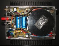
My attempt at a compact Bridged LM4780 Stereo amplifier in an old die-cast box, 220mm x 145mm (190mm including heatsinks) x 50mm high.
Made mostly from junk I had lying around.
Home made single sided PCB,s
The transformer is Mu-Metal shielded
4x 4,700uf/50v capacitors + 4x 1000uf/63v caps on PCB (one under each board)
DC protection circuit and relay at rear + Speaker fuses
65 + 65w RMS 8 ohm
85 + 85w RMS 4 ohm
130w RMS one channel driven for 1min test.
Given the transformer is so close I was surprised there is no hum and despite not using hi-end components (would not fit) the sound quality is still very pleasing.
Attachments
" ... Given the transformer is so close I was surprised there is no hum ..."
'Cause the transformer is enclosed in a metal case of its own ?? = a quality shield close to the windings =")
As long as the mu-metal transformer case remains grounded to the chassis = very little hum.
Q&A: how did you fasted the heat sinks to the case? ... and do the heat sinks ever get warm ??
'Cause the transformer is enclosed in a metal case of its own ?? = a quality shield close to the windings =
As long as the mu-metal transformer case remains grounded to the chassis = very little hum.
Q&A: how did you fasted the heat sinks to the case? ... and do the heat sinks ever get warm ??
FastEddy said:The more power supply cacacitance and filteration, the better the sound.
One of the tenants of the gain-clone concept is that you can have too much C in the PS. 1000-1500 uF/rail seems to be the sweet spot from the experimenting people have done.
dave
planet10 said:
One of the tenants of the gain-clone concept is that you can have too much C in the PS. 1000-1500 uF/rail seems to be the sweet spot from the experimenting people have done.
dave
Ok, but my boards sound better with the extra capacitors. I am almost new to GC, but my ears are still good, and have done a long career...

The Heatsinks are attached with 6x screws into taped threads in the case and a strip of copper buss-bar helps spread the heat from the chip.
There is about 5w at idle so the heatsinks are just warm but get quite warm almost hot on hot days when the amp is pushed hard for long periods even into 8 ohm, I think the amplifier would over heat under the same conditions into 4 ohm.
PS rail voltages are +/-42v, I would have liked it a bit lower but I have 12 of these transformers from old computer terminals and wanted to use one.
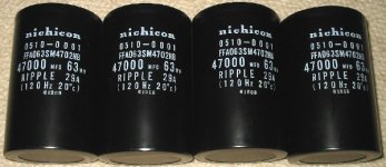
VLSI said:Should I put these in my next GC?
Came from a bit of telecom equipment I recently trashed (also had in it 12x 47,000/50v capacitors as well)
These Nichicon are nice.VLSI said:PS rail voltages are +/-42v, I would have liked it a bit lower but I have 12 of these transformers from old computer terminals and wanted to use one.
If you were not on the other side of the world I would have asked you to send here some of these trafos...
Kooka said:
You mean that the sound of my GC got worse? I had the opposite impression.
I didn't say anything about the sound of your GC
, I've seen several disscussions on caps in GCPSU on this forum, but common concent seems to be that more capacitance improves the amps abilities in the lower frequencies, but also slows it down, ruining the immidiacy (spelled rigth ?) the rythmic flow that makes the original my favourite, in spite of it's obvious problems n the bass area.superhkm said:
I didn't say anything about the sound of your GC
Ah, we are at the point: I haeard the same boards without and with the extra caps. The impression is exactly in the way you describe them, but since the improved bass section is clearly audible, and the slowing down of dynamic is really on the little size, I assume one thing: if an amp is lacking in basses but quite dynamic, an improvement in the bass section and a little reduction in dynamicity transalte in a general improvement of sound.
Making a long story short: after hearing the boards without and with the extra caps, I will leave the caps there
I have experimented with capacitor values from 1000uf to 50,000uf and I would have to say that on the whole more is better.
What really seemed to help are 4.7uf – 10uf Polypropylene capacitors as close to the chip as practical.
I have built 9 chip amps all different parts and layouts and they all sound basically the same, even with a listening panel of friends (2 of which are using my old GC’s full time) agree there is not much difference.
The biggest breakthrough to my ears has to be the LM4702, Even my rough prototype has far better imaging and detail than any GC I have built.
I am very excited about this chip and hope to hear much more from the DIY community.
BTW Just for fun I took the entire front end out of an old LUXMAN 5L15 amplifier yesterday (leaving just the output transistors, driver transistors and VBE multiplier) and replaced it with a LM4702 and the improvement in sound was absolutely incredible.
I have 2x 5L15,s so it is easy to compare them.
It may be just a question of taste, in sound and in music.
My nr.1 stereo system is in the familiy livingroom, and plays a lot of acoustic jazz and classical. If I crank up Deep Purple I'm usually in the car, or with headphones in front of the pc.
ps. it may be time to leave this thread for it's rightful purpose..ds.
My nr.1 stereo system is in the familiy livingroom, and plays a lot of acoustic jazz and classical. If I crank up Deep Purple I'm usually in the car, or with headphones in front of the pc.
ps. it may be time to leave this thread for it's rightful purpose..ds.
stk4048XI
My first Chip amp after building a few tube amps and it suprised me very much.
I used the stk4048XI and it behaved perfectly.
I even designed it on vero board and had no troubles at all.
I completed a stereo amp with built in passive pre amp with four inputs.
Extremely easy to build. Very powerful.
I fully documented the project with board layouts and pictures to reconstruct the amp.
Attachments
My_Ref_C being reboxed.
Also upgraded a number of elco caps to low ESR models, ceramics to cog and bypassed some other, and found 2 caps that were 470nf instead of 1nf, which I think explains my previous heat issues.
This rear part slides into a box from the rear... I will post pictures of the box later... just took a small smoke break quickly inbetween installing PCBs.
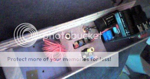

The heatsinks 2.5C/W 10cm x 10cm x 5cm x2
Also upgraded a number of elco caps to low ESR models, ceramics to cog and bypassed some other, and found 2 caps that were 470nf instead of 1nf, which I think explains my previous heat issues.
This rear part slides into a box from the rear... I will post pictures of the box later... just took a small smoke break quickly inbetween installing PCBs.
The heatsinks 2.5C/W 10cm x 10cm x 5cm x2
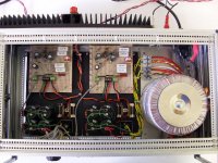
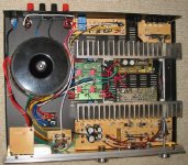
Almost finished my Bridged LM4780
Just need to remove the old pre-amp and make a timber front panel?
It is built in the chassis of a wrecked KODA 260 amplifier (A2760 in Australia) from DSE.
I was able to use the 300va transformer, 4x 10,000uf filter caps, DC protection circuit and input selector, New heatsinks though as the originals where too small.
The pre amp is disconnected, Just using the volume control till I can get a good quality Alps.
I designed and home made the single sided PCB’s
It has a regulated 5A PS (tested limit 7A) using 2x LMS 1585-1.5v regulators protected from capacitor charging inrush and output shorts by 2x 9.1v/50w zener diodes. PS input is 45v output is adjustable with a 10T trimmer in the ground lead and set to 38v.
The sound is very sweet and smooth almost valve like in quality, Probably the best sounding LM3886/LM4780 amp I have built, I really like using this amp.
I have used the amplifier modules before but they have not sounded this good. (Must be the regulated power supply??)
RMS outputs are 75w+75w 8ohm, 110w + 110w 4ohm (voltage regulators drop out with 2x 4ohm load) 75w one channel 8ohm and 140w one channel 4ohm
Attachments
- Home
- Amplifiers
- Chip Amps
- Chip Amp Photo Gallery