I fail to comprehend why you should be so surprised. Whilst I wouldn't for a moment consider keeping the current wiring for 'production' use, nor let anybody other than myself near it, it's a solid connection that wouldn't come lose short of pulling hard enough to snap the wire. I can't see how anything could have gone wrong unless I purposefully started tugging at wires & putting my fingers where I know they shouldn't be put & if that were the case I wouldn't let myself near a 9V battery let alone 240V AC.
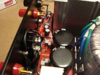
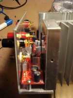
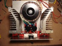
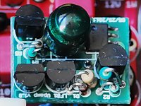
My LM3886 amp
I thought I had posted these before in the Gallery, but apparently not....
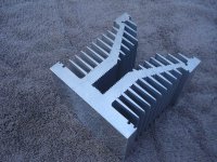
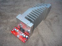
The heat sink is overkill--left over from some Class A amp projects I've completed. Same goes for the Antek transformer. Despite the size of the heatsinks (and what you see was originally ONE heatsink, that I halved for both channels of this project) and transformer, I wanted to make this a relatively compact amp. As such, all the other aspects of this amp (PCB layout, wiring, etc) are pretty compact--the amp's footprint is 9" x 9".
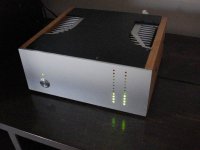
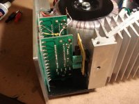
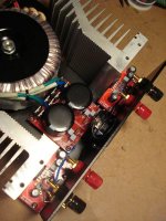
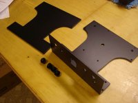
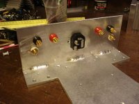
The PCBs are from ChipAmp. Chassis is a homebuilt one, with the bottom plate (3/16" aluminum) and rear apron (1/8" aluminum) welded together to minimize need for nuts/bolts/brackets. The chassis (top/bottom plates) were finished in matte black powder coat. Most wiring for this amp was routed under the respective PCBs to reduce the "visual clutter".
The LED VU meters are from eBay, and the front panel is from Front Panel Express. Cabinet side plates are 1/2" thick maple.
Easy build, with no problems. The compact chassis gave me some soldering challenges. This little amp sounds great--it probably will not replace my Class A amps, but it's a good add to the audio equipment collection!
Ken
I thought I had posted these before in the Gallery, but apparently not....
The heat sink is overkill--left over from some Class A amp projects I've completed. Same goes for the Antek transformer. Despite the size of the heatsinks (and what you see was originally ONE heatsink, that I halved for both channels of this project) and transformer, I wanted to make this a relatively compact amp. As such, all the other aspects of this amp (PCB layout, wiring, etc) are pretty compact--the amp's footprint is 9" x 9".
The PCBs are from ChipAmp. Chassis is a homebuilt one, with the bottom plate (3/16" aluminum) and rear apron (1/8" aluminum) welded together to minimize need for nuts/bolts/brackets. The chassis (top/bottom plates) were finished in matte black powder coat. Most wiring for this amp was routed under the respective PCBs to reduce the "visual clutter".
The LED VU meters are from eBay, and the front panel is from Front Panel Express. Cabinet side plates are 1/2" thick maple.
Easy build, with no problems. The compact chassis gave me some soldering challenges. This little amp sounds great--it probably will not replace my Class A amps, but it's a good add to the audio equipment collection!
Ken
Attachments
-
 Chip1.JPG88 KB · Views: 2,301
 -
 Final5.JPG42.2 KB · Views: 1,118
 -
 Chip43.JPG52.9 KB · Views: 776
 -
 Chip36.JPG68.6 KB · Views: 701
 -
 Chip34.JPG58.7 KB · Views: 589
 -
 Chip32.JPG37.7 KB · Views: 692
 -
 Chip24.JPG47.7 KB · Views: 2,135
 -
 Chip19.JPG50.6 KB · Views: 2,191
 -
 Chip13.JPG69 KB · Views: 2,239
 -
 Chip7.JPG80 KB · Views: 2,251
I hate it, hate it, hate it.
Eerrr..... that's HATE, only in the BEST of ways, right?
Drool!
Very, very, very nice!!! The heat sinks do look amazing!
Happy Holidays & Merry Christmas to all!
I thought I had posted these before in the Gallery, but apparently not....
The heat sink is overkill--left over from some Class A amp projects I've completed. Same goes for the Antek transformer. Despite the size of the heatsinks (and what you see was originally ONE heatsink, that I halved for both channels of this project) and transformer, I wanted to make this a relatively compact amp. As such, all the other aspects of this amp (PCB layout, wiring, etc) are pretty compact--the amp's footprint is 9" x 9".
The PCBs are from ChipAmp. Chassis is a homebuilt one, with the bottom plate (3/16" aluminum) and rear apron (1/8" aluminum) welded together to minimize need for nuts/bolts/brackets. The chassis (top/bottom plates) were finished in matte black powder coat. Most wiring for this amp was routed under the respective PCBs to reduce the "visual clutter".
The LED VU meters are from eBay, and the front panel is from Front Panel Express. Cabinet side plates are 1/2" thick maple.
Easy build, with no problems. The compact chassis gave me some soldering challenges. This little amp sounds great--it probably will not replace my Class A amps, but it's a good add to the audio equipment collection!
Ken
Very, very, very nice!!! The heat sinks do look amazing!
Happy Holidays & Merry Christmas to all!
I saw your post2003 pics earlier. Were they on a remote server? Were they inadvertently deleted?
Andrew...... I had posted a separate short, sweet "build thread" in the ChipAmp forum about two months ago--but failed to post some of those pics to the Gallery. I'm guessing you stumbled upon that short build thread posting sometime over the last two months....
Last edited:
Nice chassis. You did well to drill those VU holes straight!
Tripmaster..... I hate to divulge "state secrets", but the front panel holes were drilled by the Front Panel Express company. If you've never used them, they are a great service. You download their "Front Panel Designer" software, and lay out your panel on your PC. The software also computes cost. You then Email to FPE, and they do the rest. Very quick response/shipping, and a good quality product!
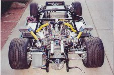
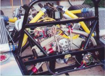
Having said that, I actually do a lot of metal fabrication work, but mostly on the sports racing cars I design and build (that's another hobby, for another time, and for another "car related" website....!).
But now, back to the ChipAmp gallery pics.... Didn't mean to hijack the thread!
Attachments
hey, what kind of dyn(o) range do you get on those non-chip amps, canam?
Let's see....... On my Pass DIY F5 amp, I get about 25 watts per channel. On my "other hobby", I get 1,053 HP (corrected for sea level on a Superflow dyno) out of 355 cu inches, at 21 lbs boost. And BOTH make great music to my ears!
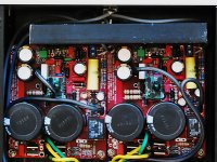
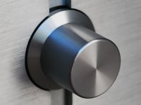
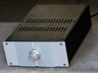
A MyRef Rev E assembled in an off-the-shelf 8Audio anodized aluminium case.
1. Front quarter view
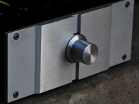
2. Front panel - cast aluminium, milled and chemically etched.
3. Potentiometer knob
4. MyRef Rev E monoblock boards, V1.3
5. Detail of a Rev E monoblock with LF01 Class-A discrete hybrid opamp module
6. Detail of LF01 module, showing styroflex rail-to-rail bypass
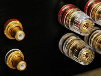
7. Rear panel gold-plated connectors
1. Front quarter view
2. Front panel - cast aluminium, milled and chemically etched.
3. Potentiometer knob
4. MyRef Rev E monoblock boards, V1.3
5. Detail of a Rev E monoblock with LF01 Class-A discrete hybrid opamp module
6. Detail of LF01 module, showing styroflex rail-to-rail bypass
7. Rear panel gold-plated connectors
Attachments
-
 lf01_6x4.jpg84.7 KB · Views: 872
 -
 myref13_reve_lf01_12x9.jpg312 KB · Views: 1,038
 -
 myref_boards_12x9.jpg320.8 KB · Views: 1,055
 -
 myref_knob_12x9.jpg108.6 KB · Views: 1,928
 -
 myref_face1_12x9.jpg126.6 KB · Views: 2,019
 -
 myref_front1_12x9.jpg188.4 KB · Views: 2,183
 -
 myref_connectors_12x9.jpg173.1 KB · Views: 793
Last edited:
That looks great Siva.
How are you implementing the pot and I guess I missed the styroflex rail to rail story. Did you post about that specifically or as just part of the entire unit?
Hi Bob - the pot is just a stock Philips dual-gang 10k carbon-track linear with a short 3.5mm diameter shaft. I used a plastic 3.5-to-5 mm adapter sleeve to be able to fit the 8Audio aluminium knob to it without any wobble/eccentricity.
There's enough space at the rear of the case for a passive attenuator like a Lightspeed, and another option is a low-profile stepped attenuator in place of the potentiometer.
The Styroflex cap is a chance discovery last week - this is a TSC 8.2nF 100V styroflex with 2.5mm radial leads. It fits snugly in an LF01 in place of the 3.3nF Wima MKS02 I was using earlier. I can't say that there is any difference in audible sonics, but it doesn't hurt either, so I'll leave it in for now and audition it carefully. This is effectively a bypass for C7/C23.
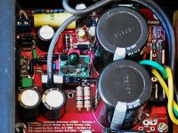
I noticed you did not use the second ground near the LED pad. Is there any advantage/disadvantage in using that other than convenience? I'm planning to use all four wires straight from the toroid.
My trafo has a 24-0-24 secondary with just 3 wires, going to AC1, PGND and AC2 respectively, so I don't need the second PGND connector. If you have dual secondaries (4-wire, i.e. 2x 24-0), then the second PGND connector is useful.
Last edited:
- Home
- Amplifiers
- Chip Amps
- Chip Amp Photo Gallery