Äà, äåëàþ, â íàëè÷èè èìåþòñÿ 10 ïëàò ïîä ýòîò óñèëèòåëü. Áîëåå ïîäðîáíî òóò
http://www.vegalab.ru/forum/showthread.php?t=5842
http://www.vegalab.ru/forum/showthread.php?t=5842
Now thats what I call progress. Great work!!! Lets see how long before this catches the ire of the "AD815 gate keeper". After all he used it first, and he requires his permission. ") Just kidding.
Just kidding.
Very well done ciruit I like the servos and the SMD layout. Excellent execution. A real insipration.
Thanks for sharing. I am sure it is a great headamp.
Cheers!
Russ
Just kidding.Very well done ciruit I like the servos and the SMD layout. Excellent execution. A real insipration.
Thanks for sharing. I am sure it is a great headamp.
Cheers!
Russ
Great work Maxim! I like the PS section.
I'm listening to something similar and AD815 is a very good amplifier for high(er) impedance headphones.
DC Servo is a must for AD815 ARB version. I have got about output
300mV offset voltage without it . Trough hole is better but it's hard to find.
AD815 is a current feedback amplifier so feedback resistors values should be keep as low as possible.
And what with the clik and pop noise on startup and turn off?
This is another nice current feedback amplifier. This time from Linear
I'm listening to something similar and AD815 is a very good amplifier for high(er) impedance headphones.
DC Servo is a must for AD815 ARB version. I have got about output
300mV offset voltage without it
. Trough hole is better but it's hard to find.AD815 is a current feedback amplifier so feedback resistors values should be keep as low as possible.
And what with the clik and pop noise on startup and turn off?
An externally hosted image should be here but it was not working when we last tested it.
This is another nice current feedback amplifier. This time from Linear
An externally hosted image should be here but it was not working when we last tested it.


Excellent job! This is a very nice implementation of this super copyrighted registered trademarked, all rights reserved current feedbacck opamp (he he I couldn't resist) The PCB design is nice and professional! How does that servo seem to handle the DC offset across the entire range of the pot?
G.
(he he I couldn't resist) The PCB design is nice and professional! How does that servo seem to handle the DC offset across the entire range of the pot?G.
"But two pays and collections of details under them will how much cost" said http://babelfish.altavista.com to me. Didn't tell me any particular 
Mr. Professor, english is the main language here but if you have some problems with you could always try Altavista.
A hint to everybody else who want to read the russian forum, use Altavista for this also, works rather good, much better than french
Mr. Professor, english is the main language here but if you have some problems with you could always try Altavista.
A hint to everybody else who want to read the russian forum, use Altavista for this also, works rather good, much better than french
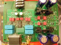
I notice at the right phono connector that you have a "meander" trace. Why is that? Do you have a groundplane on solderside?
A purpose of meander is alignment of the stray capacitance of the input circuits in both channels. Actually it does not influence to sound (I don't hear any difference), but I made it only as decorative element. This PCB has a split groundplane on bottom layer
- Status
- This old topic is closed. If you want to reopen this topic, contact a moderator using the "Report Post" button.
- Home
- Amplifiers
- Chip Amps
- It's my AD815 headamp