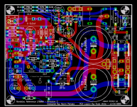
Its been a while now since I first laid out a PCB for Mauro's "My Reference" revision C. The first layout was largely a product of taking Mauro's suggestions for a monobloc version and running various iterations past the forum to get as much input as possible.
Well since then literally hundreds of people (maybe more I do not know) have built or are building MyRef. This has given me even more feedback about the layout and spawned some new ideas. Also Mauro has given some guidence on how to make the circuit, and the layout a little better. I have taken this new experience and applied it to a new layout. Here it is for your pleasure.
Major changes:
1) More flexible input and led interfaces allow for terminal blocks, pinheaders, IDC connectors, etc..
2) Bigger more flexible cap space to allow for MKP cap on input.
3) Allowance on power supply for monoluthic rectifier (as in the original) or TO220 types such as MUR860.
4) Additonal output solder holes for direct soldering of large gage wire to the PCB for OUT and OUT-GND.
You can still build the circuit exactly as before, or take advantage of the new features, its your choice. You can also still build the circuit as "Rev A" without much fuss.
Also, the layout has been changed to eliminate as much as possible any sharp angles in the traces. This may not do anything, but I like it better.") Also many traces are widened, and some little things like silkscreen changes have also been made.
Also many traces are widened, and some little things like silkscreen changes have also been made.
Only circuit features which adhere to the circuit designer's philosophy and intent have been included in the layout, and nothing else ever will be included by me as the circuit is in my opinion, simply put, often imitated, never surpassed.
Thanks to Mauro for a design which will forever change the way we look at chip amps.
Note: This is the 2 side version which Brian and I have produced, but I am working on a single side version which I will make PDFs for and share freely so those who would like to etch it for yourselves can.
Here it is:
Cheers!
Russ
Well since then literally hundreds of people (maybe more I do not know) have built or are building MyRef. This has given me even more feedback about the layout and spawned some new ideas. Also Mauro has given some guidence on how to make the circuit, and the layout a little better. I have taken this new experience and applied it to a new layout. Here it is for your pleasure.
Major changes:
1) More flexible input and led interfaces allow for terminal blocks, pinheaders, IDC connectors, etc..
2) Bigger more flexible cap space to allow for MKP cap on input.
3) Allowance on power supply for monoluthic rectifier (as in the original) or TO220 types such as MUR860.
4) Additonal output solder holes for direct soldering of large gage wire to the PCB for OUT and OUT-GND.
You can still build the circuit exactly as before, or take advantage of the new features, its your choice. You can also still build the circuit as "Rev A" without much fuss.
Also, the layout has been changed to eliminate as much as possible any sharp angles in the traces. This may not do anything, but I like it better.
Also many traces are widened, and some little things like silkscreen changes have also been made.Only circuit features which adhere to the circuit designer's philosophy and intent have been included in the layout, and nothing else ever will be included by me as the circuit is in my opinion, simply put, often imitated, never surpassed.
Thanks to Mauro for a design which will forever change the way we look at chip amps.
Note: This is the 2 side version which Brian and I have produced, but I am working on a single side version which I will make PDFs for and share freely so those who would like to etch it for yourselves can.
Here it is:
Cheers!
Russ
Attachments
Then there is this....
Which I would be most grateful if someone could translate to english.
PS Description
Which I would be most grateful if someone could translate to english.
PS Description
Google translation, my apologies to Mauro as it is probably complete murdered...:
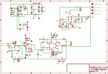
Measures of disturbance of rectification my_ref Of Mauro Penasa After a series of exchanges of opinions with several get passionate, have decided to make some preliminary tests to you on My_REF revC, in section PSU (Power Supply Unit). The cue is born from the new tendencies of dimensioning of the diode valves rectifiers and Condensers of levelling and bypass, that they carry to use fast or ultrafast diode valves with techniques of bypass "snubber". Since the rule wants that to demonstrate the things asserted is who proposes to them, I will not take care myself to analyze to bottom the cited techniques, but to demonstrate to the reasons of dimensioning of My_ref and their effectiveness. In consequence, the necessity not to use more sophisticated techniques becomes obvious also... GND +VCC1 C8 10000uF C3 10000uF R4 1K 1W R1 1K 1W ZD2 12V 1W ZD1 12V 1W -12V1 +12V1 D1 P_D C5 100nF Cfilter Rfilter 10nF 2K FFT - VCC1 C6 100uF 25V C11 100uF 25V Fig1: Circuit of measure of the noise of commutation of the diode valves rectifiers. Filter RC limits the amplitude of marks them to 50Hz, in order to evidence the spikes of the diode valves. This method traces that one used from George Korga in its tests on the forum DIYaudio.com the used transformer is a toroidal Talema 225V 230/25+25Vac, connected directly to the relati to you faston AC. Fig2: Phantom of frequency of marks them between Vac1 and GND of the rectifying bridge My_ref, captured with filter 10n+2Kohm. Medium value. The condenser from 100nF between AC1 and AC2 dampens the spike to vhf and door the peak of resonance trafo-CAP diode valves to approximately 30Khz. All members HF is absorbed from the risonante net. Fig3: Phantom like fig2 but to 36W 8ohm 1Khz. Like famous, this characteristic curve is enough independent from the cargo of the amplifier (increase of little dB in zone 50Khz), and can be modified solo from the value of the condenser between Vac1 and Vac2, and from the inductance of the secondary winding of the transformer. To second of the transformer model this resonance it can be found between approximately 15Khz and 30Khz. The necessity emerges clear to decide of a group of condensers of filtratura with good efficiency to these frequencies. A ELcap of good quality from 10000µF 50V arranges of an optimal fine efficiency and beyond 20Khz, for which alone it is in a position to eliminating all the residual ones of rectification. The local added one of ELcap from 220uF low ESR allows to increase this fine efficiency beyond the 200Khz... Various it is the situation if to the dimensions and the ability to the Elcap are increased. A ELcap from 20000µF difficultly succeeds to absorb the peaks of commutation of the diode valves, for which it must be made resorted to more sophisticated techniques of filtratura is on the diode valves that on the PSU... A useful system can be the use of ELcap of smaller multiple ability or with differentiated ability (scales of 1/4 or 1/8 of ability), but the inductance series of the layout reduces the theoretical efficiency of these nets, to times creating other resonances... From this diagram the total is deduced uselessness to use more complex techniques of rectification. The use of diode valves "Fast" can reduce the amplitude of the scapito disturbance but to of a frequency increase. The efficiency of the condensers beyond the 200-500Khz diminishes in esponenziale way to these energetic levels, for which it is not possible to absorb the resonance peak completely. From the Audio point of view, to part the electromagnetic emissions of these nets (that these behaviors in AC can influence the amplification sections) do not have no value. The part of the circuit that must be determine the proportions correctly is section DC. Eventual the residual ones of rectification can modulate mark them useful, increasing the distortions are statics that dynamic. Fig4: Phantom of frequency of marks them present on the positive tension (between +VCC and GND) of feeding of My_ref, without marks them in income. Famous the classic spectral distribution of the tooth of is sawed provoked from the partial discharge of the Elettrolitici to mains net frequency. Beyond the 6Khz practically they do not exist marks them of disturbance. To notice that to vlf it disturbs they are you become lean from the CMRR (common mode rejection ratio) that in the modern ones amp it is much elevating within the cited frequencies. The important thing is to maintain limits disturbs to you beyond the 6Khz.... As it is looked at the elettrolitici (and the layout drawn near) absorb in way total the peak of disturbance of commutation of the diode valves. This job comes completely carried out from the large condensers from 10000 µF. The rest of the bypass is the much most useful one in order to absorb the modulations that are created during the job of the amp... Fig5: Diagram FFT of the modulation of +VCC (between +Vcc and GND), on My_ref, with 8 cargo ohm to 36Wrms 1Khz. To vlf (< 4Khz) the same tooth envelope is found of saws, increased because of the greater modulation demanded from the increase of dispersed medium current from the PSU. Although this, to notice the fast decay of the disturbance beyond the 5Khz. Practically remains only the harmonicas of marks amplified them. The peak to 28Khz is caused from the system of measure (PC). The thing that I think more important is the depth of harmonic modulation of marks amplified them. Famous the fundamental one to 1 Khz to approximately -25dB, continuation from all the series of harmonicas, with prevalence of the equal harmonicas. This diagram does not arouse particular alarmisms, because it demonstrates a shape of "jam" caused from the instantaneous decrease of the feeding to the increase of escape current. A amp modern it does not have difficulty "to absorb" these conditions, using the NFB (local or total). It must consider that it marks them of escape has an amplitude of approximately +25 dB, for which the modulation on PSU seen from the amp is to approximately -50dB (second harmonica -60dB), for which little tens of dB of NFB in order absorbing them are enough. The critical conditions of bypass in audio band are these. The filter net must absorb to the maximum the modulations with progressive course, in way "not to overload" the performances of the amp to vhf. In order to obtain this characteristic one adequate lowland serves one stiffness of the local p0wer source within a sufficiently wide range of frequency. Fig6: Same conditions before but with mark them to 10Khz. Notare analogous course (the IMD beyond 120Khz are caused from the sampling to 330Khz with residual the harmonic ones beyond the 160Khz, and therefore not realistic). The amplitude of the harmonicas practically equal to those to 1Khz confirmation that until beyond 200Khz the net of bypass executes its job correctly. If the stiffness of the PSU increased, a modulation increase would be had... In order to obtain bonds it turns out you to these frequencies is necessary to use Elcap give approximately 100-220uF low ESR. Low the CAP to film does not have sufficient a capacitiva reattanza in order to limit the modulations, and serves exclusively or in order to dampen resonances caused from layout to a high inductance parasite, or for noise or resonances in band RF. Conclusions: An amplifier adequately filtered within the audio band of competence (10-100Khz) does not have reason to use techniques of bypass adapted for advanced frequencies to 1Mhz, to part some particular conditions, like risks of local oscillations or reduction of the local noise (thermal or electromagnetic). The use of fast or ultra fast diode valves does not have a justified technical reason, because they generate however it disturbs of commutation to most vhf. The damping of such spikes, if also of amplitude much minor is extremely critical, because necessity of nets of extremely efficient condensers to most vhf. The use of ordinary rectifiers allows to absorb the spikes using more common elements much. A weighted use of these members (fast diode valves) however can give rise to situation of noise of smaller commutation of other normal diode valve structures, in particular during the distribution of forts currents of loads. The outcomes of these analyses demonstrate that the variations of the disturbance in function of the current on this circuit do not assume such entities to justify some use it. Other element not to underrate is the necessity to execute of the PCB layout more elaborates to you in the case of a use of "discreet" diode valves of power, with the risk to increase the emissions electromagnetic. During the normal operation, an amplifier is in a position to working $R-al.meglio in presence of one low inner stiffness of the PSU, but in particular it is important that it is to delineate in the entire phantom of frequencies that reproduces. The presence of marks them "spuri" on the PSU does not have to modulate marks them useful. For this the amp it must have an adequate CMRR, and to be therefore sufficiently "immune" from these disturbs. This document goes considered one technical integration to the several descriptions of the plan "My_Ref". The outcome of the measures serves to justify some progettuali choices on which the job is based. All the conditions of exercise found on this circuit are not riproducibili with other topologies. In such sense this description does not have to be considered a guide to the planning of the PSU for amplifiers audio. M.P.
Measures of disturbance of rectification my_ref Of Mauro Penasa After a series of exchanges of opinions with several get passionate, have decided to make some preliminary tests to you on My_REF revC, in section PSU (Power Supply Unit). The cue is born from the new tendencies of dimensioning of the diode valves rectifiers and Condensers of levelling and bypass, that they carry to use fast or ultrafast diode valves with techniques of bypass "snubber". Since the rule wants that to demonstrate the things asserted is who proposes to them, I will not take care myself to analyze to bottom the cited techniques, but to demonstrate to the reasons of dimensioning of My_ref and their effectiveness. In consequence, the necessity not to use more sophisticated techniques becomes obvious also... GND +VCC1 C8 10000uF C3 10000uF R4 1K 1W R1 1K 1W ZD2 12V 1W ZD1 12V 1W -12V1 +12V1 D1 P_D C5 100nF Cfilter Rfilter 10nF 2K FFT - VCC1 C6 100uF 25V C11 100uF 25V Fig1: Circuit of measure of the noise of commutation of the diode valves rectifiers. Filter RC limits the amplitude of marks them to 50Hz, in order to evidence the spikes of the diode valves. This method traces that one used from George Korga in its tests on the forum DIYaudio.com the used transformer is a toroidal Talema 225V 230/25+25Vac, connected directly to the relati to you faston AC. Fig2: Phantom of frequency of marks them between Vac1 and GND of the rectifying bridge My_ref, captured with filter 10n+2Kohm. Medium value. The condenser from 100nF between AC1 and AC2 dampens the spike to vhf and door the peak of resonance trafo-CAP diode valves to approximately 30Khz. All members HF is absorbed from the risonante net. Fig3: Phantom like fig2 but to 36W 8ohm 1Khz. Like famous, this characteristic curve is enough independent from the cargo of the amplifier (increase of little dB in zone 50Khz), and can be modified solo from the value of the condenser between Vac1 and Vac2, and from the inductance of the secondary winding of the transformer. To second of the transformer model this resonance it can be found between approximately 15Khz and 30Khz. The necessity emerges clear to decide of a group of condensers of filtratura with good efficiency to these frequencies. A ELcap of good quality from 10000µF 50V arranges of an optimal fine efficiency and beyond 20Khz, for which alone it is in a position to eliminating all the residual ones of rectification. The local added one of ELcap from 220uF low ESR allows to increase this fine efficiency beyond the 200Khz... Various it is the situation if to the dimensions and the ability to the Elcap are increased. A ELcap from 20000µF difficultly succeeds to absorb the peaks of commutation of the diode valves, for which it must be made resorted to more sophisticated techniques of filtratura is on the diode valves that on the PSU... A useful system can be the use of ELcap of smaller multiple ability or with differentiated ability (scales of 1/4 or 1/8 of ability), but the inductance series of the layout reduces the theoretical efficiency of these nets, to times creating other resonances... From this diagram the total is deduced uselessness to use more complex techniques of rectification. The use of diode valves "Fast" can reduce the amplitude of the scapito disturbance but to of a frequency increase. The efficiency of the condensers beyond the 200-500Khz diminishes in esponenziale way to these energetic levels, for which it is not possible to absorb the resonance peak completely. From the Audio point of view, to part the electromagnetic emissions of these nets (that these behaviors in AC can influence the amplification sections) do not have no value. The part of the circuit that must be determine the proportions correctly is section DC. Eventual the residual ones of rectification can modulate mark them useful, increasing the distortions are statics that dynamic. Fig4: Phantom of frequency of marks them present on the positive tension (between +VCC and GND) of feeding of My_ref, without marks them in income. Famous the classic spectral distribution of the tooth of is sawed provoked from the partial discharge of the Elettrolitici to mains net frequency. Beyond the 6Khz practically they do not exist marks them of disturbance. To notice that to vlf it disturbs they are you become lean from the CMRR (common mode rejection ratio) that in the modern ones amp it is much elevating within the cited frequencies. The important thing is to maintain limits disturbs to you beyond the 6Khz.... As it is looked at the elettrolitici (and the layout drawn near) absorb in way total the peak of disturbance of commutation of the diode valves. This job comes completely carried out from the large condensers from 10000 µF. The rest of the bypass is the much most useful one in order to absorb the modulations that are created during the job of the amp... Fig5: Diagram FFT of the modulation of +VCC (between +Vcc and GND), on My_ref, with 8 cargo ohm to 36Wrms 1Khz. To vlf (< 4Khz) the same tooth envelope is found of saws, increased because of the greater modulation demanded from the increase of dispersed medium current from the PSU. Although this, to notice the fast decay of the disturbance beyond the 5Khz. Practically remains only the harmonicas of marks amplified them. The peak to 28Khz is caused from the system of measure (PC). The thing that I think more important is the depth of harmonic modulation of marks amplified them. Famous the fundamental one to 1 Khz to approximately -25dB, continuation from all the series of harmonicas, with prevalence of the equal harmonicas. This diagram does not arouse particular alarmisms, because it demonstrates a shape of "jam" caused from the instantaneous decrease of the feeding to the increase of escape current. A amp modern it does not have difficulty "to absorb" these conditions, using the NFB (local or total). It must consider that it marks them of escape has an amplitude of approximately +25 dB, for which the modulation on PSU seen from the amp is to approximately -50dB (second harmonica -60dB), for which little tens of dB of NFB in order absorbing them are enough. The critical conditions of bypass in audio band are these. The filter net must absorb to the maximum the modulations with progressive course, in way "not to overload" the performances of the amp to vhf. In order to obtain this characteristic one adequate lowland serves one stiffness of the local p0wer source within a sufficiently wide range of frequency. Fig6: Same conditions before but with mark them to 10Khz. Notare analogous course (the IMD beyond 120Khz are caused from the sampling to 330Khz with residual the harmonic ones beyond the 160Khz, and therefore not realistic). The amplitude of the harmonicas practically equal to those to 1Khz confirmation that until beyond 200Khz the net of bypass executes its job correctly. If the stiffness of the PSU increased, a modulation increase would be had... In order to obtain bonds it turns out you to these frequencies is necessary to use Elcap give approximately 100-220uF low ESR. Low the CAP to film does not have sufficient a capacitiva reattanza in order to limit the modulations, and serves exclusively or in order to dampen resonances caused from layout to a high inductance parasite, or for noise or resonances in band RF. Conclusions: An amplifier adequately filtered within the audio band of competence (10-100Khz) does not have reason to use techniques of bypass adapted for advanced frequencies to 1Mhz, to part some particular conditions, like risks of local oscillations or reduction of the local noise (thermal or electromagnetic). The use of fast or ultra fast diode valves does not have a justified technical reason, because they generate however it disturbs of commutation to most vhf. The damping of such spikes, if also of amplitude much minor is extremely critical, because necessity of nets of extremely efficient condensers to most vhf. The use of ordinary rectifiers allows to absorb the spikes using more common elements much. A weighted use of these members (fast diode valves) however can give rise to situation of noise of smaller commutation of other normal diode valve structures, in particular during the distribution of forts currents of loads. The outcomes of these analyses demonstrate that the variations of the disturbance in function of the current on this circuit do not assume such entities to justify some use it. Other element not to underrate is the necessity to execute of the PCB layout more elaborates to you in the case of a use of "discreet" diode valves of power, with the risk to increase the emissions electromagnetic. During the normal operation, an amplifier is in a position to working $R-al.meglio in presence of one low inner stiffness of the PSU, but in particular it is important that it is to delineate in the entire phantom of frequencies that reproduces. The presence of marks them "spuri" on the PSU does not have to modulate marks them useful. For this the amp it must have an adequate CMRR, and to be therefore sufficiently "immune" from these disturbs. This document goes considered one technical integration to the several descriptions of the plan "My_Ref". The outcome of the measures serves to justify some progettuali choices on which the job is based. All the conditions of exercise found on this circuit are not riproducibili with other topologies. In such sense this description does not have to be considered a guide to the planning of the PSU for amplifiers audio. M.P.
Russ White said:
but I am working on a single side version which I will make PDFs for and share freely so those who would like to etch it for yourselves can.
Russ
Very interesting....very good. Thanks
2x18 Volt transformer
Hi Russ,
to be flexible with 4 Ohm and 8 Ohm loudspeakers I want to use an 2x18 Volt or 2x20 Volt transformer with the RefCKit. Do I have to change something in the layout due to the limited voltage?
Maybe an improvement for next layouts:
In my opinion wire wound resistors in signal path are not the best choice. There are a lot high quality (Manganin etc.) resistors on the market which have TO247 packages. You should bring the resistor mounting holes to the front of the PCB so that mounting of TO247 resistor directly on the heatsink will be possible.
Arne
gengis said:Russ,
When will we see the new layout PCB made? Any time projection?
Hi Gengis,
The PCBs have been made, just waiting for them to be shipped to me, it should be no more than two weeks now, and probably more like a week.
Cheers!
Russ
The circuit has been tested very thoroughly with a single sided version and the previous production PCBs, but since these are two sided PCBs(which I do not like to etch myself) I will not have the oportunity to build a production version until the PCBs get here.
The new PCB is not a large change from the original, so there should be no issues. But the first thing I do when I get in a set of PCBs is electrically check them and then build one up quickly to be sure they are OK.
Cheers!
Russ
The new PCB is not a large change from the original, so there should be no issues. But the first thing I do when I get in a set of PCBs is electrically check them and then build one up quickly to be sure they are OK.
Cheers!
Russ
Patience... Soon..... until then the old single side layout is perfectly adequate.
You can get them here:
http://www.diyaudio.com/forums/showthread.php?postid=738689#post738689
Soon..... until then the old single side layout is perfectly adequate. You can get them here:
http://www.diyaudio.com/forums/showthread.php?postid=738689#post738689
- Status
- This old topic is closed. If you want to reopen this topic, contact a moderator using the "Report Post" button.
- Home
- Amplifiers
- Chip Amps
- My new monobloc layout for Mauro Penasa's MyRef Rev. C