Hi,
Just to clarify I have two power transformers:
One (two separated windings and no centred tap):
12Vac/3.3A
12Vac/3.3A
Another (two separated windings and no centred tap):
12Vac/3.3A
12Vac/3.3A
I don´t have any 24Vac transformer.
(att. IGC schematic)
Katapum
Just to clarify I have two power transformers:
One (two separated windings and no centred tap):
12Vac/3.3A
12Vac/3.3A
Another (two separated windings and no centred tap):
12Vac/3.3A
12Vac/3.3A
I don´t have any 24Vac transformer.
(att. IGC schematic)
Katapum
Attachments
Katapum said:Hi,
Just to clarify I have two power transformers:
One (two separated windings and no centred tap):
12Vac/3.3A
12Vac/3.3A
Another (two separated windings and no centred tap):
12Vac/3.3A
12Vac/3.3A
I don´t have any 24Vac transformer.
Put the secondaries of each transformer in series, that will give you two transformers with 24V. One for + and one for -.
Take
Hi all,
I built the amplifier. It’s incredible bad. I need to turn the pot at 3 o’clock to get some power (but not too much). Maybe I have done something wrong. The amplifier worked with 95dB diy open baffle speakers.
I have also a 300B tube amplifier (9W) and it has much more power.
What do you think?
Amplifier also has a little hum problem but I think it’s because the power input is too near input line and output speakers. Am I right?
How can find winding transformer phase (I have only a DMM)?
Katapum
I built the amplifier. It’s incredible bad. I need to turn the pot at 3 o’clock to get some power (but not too much). Maybe I have done something wrong. The amplifier worked with 95dB diy open baffle speakers.
I have also a 300B tube amplifier (9W) and it has much more power.
What do you think?
Amplifier also has a little hum problem but I think it’s because the power input is too near input line and output speakers. Am I right?
so you will need to make sure you know the phase.
How can find winding transformer phase (I have only a DMM)?
Katapum
Hi Katapum,
12V secondary (AC) will give you about 16V rail (DC). Check the chip documentation (rail voltage vs power), I think 12VAC will give you at least 12W, and with your sensitive speaker this may be enough. You can improve a bit tho by using pre-amp.
But you can also get 24V secondary by connecting two 12V secondaries together. So, two 12V secondaries become one 24V secondary. Simply connect the 2 centermost cables of the 0-12V-0-12V to get 0-24V (Then you can connect the 2 transformers to get for example 24V-CT-24V). If you cannot locate the centermost cables, make sure you can locate each secondary of 0-12V (different secondaries have no interconnection so no voltage between them) and then simply try any connection between 2 secondaries and measure the output. If you get 24V, you don't have phase problem.
Hi,
Big question could you check it for me?
PS: It´s a linear 100k pot.
Katapum
Have you got all three wires of the pot hooked up correctly?
Big question could you check it for me?
PS: It´s a linear 100k pot.
Katapum
Attachments
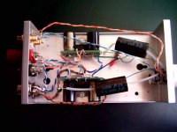
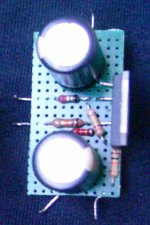
i could not but notice you used pieces of perf board for the chip amps.
I'd check if you did not switch input and feedback resistor.
If you did, max output voltage would not be 16 volts but 1/16th.
If your loudspeakers are really that sensitive you'd still have them produce sound with such extreme feedback.
At first i used 300VA toroids for the GC kits i got from BrianGT.
Then switched to 225VA, 160VA and 80VA per channel.
imo, can't say that using bigger toroids is worth it.
Tried the GCs on junk speakers first, then big 90 dB/W vifa's, then 86 dB/W ELS63s.
Plenty power on 25Vac, 22Vac and 18Vac.
Hi katapum, I cannot see why there could be a problem with potensio. I don't remember the concept of this inverted topology, it's just that the circuit looks strange to me. But if there is something wrong with the circuit, jacco must have noticed that. So the possibility is you put wrong resistor at wrong position, like jacco would like you to check.
Hi,
I checked the entire amplifier and I think everything’s ok except the ground speakers wire. I have connected speakers ground to signal ground. So I fixed it.
Next I made two tests.
First test system:
Cdplayer
Dac (diy)
Gainclone
Speakers
It sounds very low (no power), big hum, bzzzz, ….., many noise, …...
Second test system:
Cdplayer
Dac (diy)
TVC (transformer volume control, gain=+6db)
Gainclone
Speakers
It sounds very good, a lot of power, almost no noise.
So I think gainclone has a ground problem. What do you think?
How can I fix it? (I´m a newbie).
Katapum
- Status
- This old topic is closed. If you want to reopen this topic, contact a moderator using the "Report Post" button.
- Home
- Amplifiers
- Chip Amps
- What’s the minimum power transformer required to build a gainclone amplifier?