Re: Transformer
You need only one winding of ~45 VAC. So you can use a tranny ranging 18-0-18 to 22-0-22.
These should be no problem to find in that VA range.
cheers.
(please correct me if I got confused between my projects") )
)
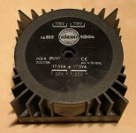
GeWa said:Anybody here that has a source for a 45V-0-45V / 5-10VA toroid transformer.
The lowest VA rating I can find with those secondaries is 160VA, and that is a bit overkill I figure?
Regards
You need only one winding of ~45 VAC. So you can use a tranny ranging 18-0-18 to 22-0-22.
These should be no problem to find in that VA range.
cheers.
(please correct me if I got confused between my projects
)You need only one winding of ~45 VAC. So you can use a tranny ranging 18-0-18 to 22-0-22.
Now that you mention it. Just had a quick look at the schematic and it's indeed only "1" secondary winding.
What's even worse, I have two 22V-0-22V / 35VA trannies in my goodies cupboard. I really feel stupid now

Thanks for the hint Hanzwillem
Regards
Attachments
I have two 22V-0-22V / 35VA trannies in my goodies cupboard. I really feel stupid now
Why stupid? Just use two secondaries in series, resulting in 44 VAC, what is perfect for the anode voltage!
BTW: I use one single torroid, about 165VA. It is including 14.8-0-14.8V (LM3875), 17.6 and 19.8 in series for the anode voltage. Then I added some windings for the 6V part (about 60 windings in my case, just try 20 windings, measure under load and calculate the needed windings, its linear).
It is a good idea, when you use the small case and relatively small heathsinks, not to use too high voltage and to much gain for the LM3875.
Franz
Hanzwillem said:There seems to be an error in the silkscreen of the PSU board.
I suspect D1,D2,D3 to be printed the wrong way. I don't see this work as a proper bridge as it is drawn at the moment...
Yes,there are silk layer missed of bridge and delay parts,I am so sorry for all troubles.I will release a 'PATH' for the psu board soon.please keep it for a while.
to wim,sorry for delay.because I couldn't surf net during weekend.
P.S.
the attached photo is the connection of 'T' network.
Attachments
Re: Transformer
yeah I have the same problem to find a proper transformer.I use a 20VA 8VAC wallwart directly powered the tube filaments and delay.A step-up transformer(200VAC to 24VAC,in reverse) converted the 8VAC to about 73VAC.
Zang
GeWa said:Anybody here that has a source for a 45V-0-45V / 5-10VA toroid transformer.
The lowest VA rating I can find with those secondaries is 160VA, and that is a bit overkill I figure?
yeah I have the same problem to find a proper transformer.I use a 20VA 8VAC wallwart directly powered the tube filaments and delay.A step-up transformer(200VAC to 24VAC,in reverse) converted the 8VAC to about 73VAC.
Zang
Mayby i missed something, but what is the need for a 45-0-45 VAC trafo? I assume you will put the windings paralel to get about 62 VDC after rectification?
Why not a trafo between 18-0-18 VAC and 22-0-22 VAC, and put the windings in serie? These trafo's are common with a much lower VA rate.
Or do i mis something?
Why not a trafo between 18-0-18 VAC and 22-0-22 VAC, and put the windings in serie? These trafo's are common with a much lower VA rate.
Or do i mis something?
GeWa said:I was under the impression that a 45-0-45 trafo was needed
For the tube which needs something between 35-0-35 & 100-0-100 @ 15+ mA or so...
dave
the third assembly is psu.
sch is here:http://www.diyaudio.com/forums/showthread.php?postid=765698#post765698
part list is here:http://www.diyaudio.com/forums/showthread.php?postid=748311#post748311
the attached is the modified assembly of psu.
attention:the ne555 chip should be set up in reverse station!
sch is here:http://www.diyaudio.com/forums/showthread.php?postid=765698#post765698
part list is here:http://www.diyaudio.com/forums/showthread.php?postid=748311#post748311
the attached is the modified assembly of psu.
attention:the ne555 chip should be set up in reverse station!
Attachments
For the tube which needs something between 35-0-35 & 100-0-100 @ 15+ mA or so...
Please, don't confuse people, this statement is completely wrong!
Again: for the tubes anode voltage, a single 35V to 45V secondary is needed. Please look at the schematics!
We use a voltage doubler circuit, so called Greinacher circuit.
Franz
Franz G said:Please, don't confuse people, this statement is completely wrong!
Again: for the tubes anode voltage, a single 35V to 45V secondary is needed. Please look at the schematics!
We use a voltage doubler circuit, so called Greinacher circuit.
Completely wrong? I could have been clearer...
From the schematic you have plus/minus 45-63VDC. The original used +/- 35VDC and we talked with supplies north of 1/-100.
True that the "official" board uses a doubler, but those that don't want to use a doubler it is a perfectly valid (some would say better) approach to use a bridge & a dual secondary trafo.
dave
Franz (or Zang), can the diodes D9+D10 (1A 1XYS 1-16D in the BOM) be replaced by the more common types 1N4007?
Thanks.
Dave, i do not understand your point. A simple and common low current trafo of 20-0-20 VAC is good for the job, with both windings in serie. What you get is 2*20VAC = 40VAC, fine in the range Franz told us.
Or do you mean something else? My English is not perfect you know.
Thanks.
Dave, i do not understand your point. A simple and common low current trafo of 20-0-20 VAC is good for the job, with both windings in serie. What you get is 2*20VAC = 40VAC, fine in the range Franz told us.
Or do you mean something else? My English is not perfect you know.
Franz (or Zang), can the diodes D9+D10 (1A 1XYS 1-16D in the BOM) be replaced by the more common types 1N4007?
Of course, it will work with 1n4007.
Franz
Franz, what is the resistor on the photo in post 31, on the backside of the PCB? Is that resistor named in the BOM or is it a fix, or additional?
And do you mean in also post 31 that the IC must by placed 180 degrees rotated than the PCB says?
Thanks again, and sorry for all my questions.
And do you mean in also post 31 that the IC must by placed 180 degrees rotated than the PCB says?
Thanks again, and sorry for all my questions.
Wim
Yes, the silk print is showing the NE555 in the wrong orientation.
About the resistor under the board: wait the answer from Zang. It seems, as he did not insert the trimmer pot and the resistor in series and replaced them by a fixed value under the board.
I am sorry about the errors on the silk print! I checked many times the solder side, but not enough the parts side. And I did not use a PSU board from Zang up to now.
Franz
Thanks again Franz.
For the resistor at the bottom off the PCB i will wait as you told (mayby if i place the trimmer pot the resistor is not nessesury).
I (and all other builders i hope) will place the NE555 at 180 degrees turned around.
Don't wory about the mistakes. if we have a good communication on this forum it will be no problem, in fact it is part of the hobby!.
Till later,
Wim
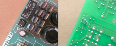
Sorry, but here i am again.
Franz, looking at your recently posted picture of the Murs on the PSU board: In the first place you changed de Murs and the C's (but thats no problem), but what is a problem I.M.O, you mounted all the Murs wrong. (cathode = anode and anode is cathode).
Please correct me if i am wrong, but i am pretty sure of it.
Best way to see it is to follow the schematic off the PSU and look good to the mountingway on your board.
If you lay down a Mur on your desk with the black plastic side in front of you, the left connectionwire is the cathode.
Hope to hear from you about it.
Till later,
Wim
- Status
- This old topic is closed. If you want to reopen this topic, contact a moderator using the "Report Post" button.
- Home
- Amplifiers
- Chip Amps
- VBITNGC building & comment