I'm currently building my LM4780's PSU, based on a double diode bridge, hence involving two ground rails , one per side.
The question is : how should they be connected together ?
- immediately at the rectifiers pins ?
- before the filtering caps
- before the snubber caps
- at the PSU terminals
- at the star ground ?
- on the chip's bypass caps pins ?
I've seen several schematics over the forum and the net but none of them precises how and why the ground rails must be connected.
On Carlos fm's High-cap PSU, the grounds of the rectifiers are immediately connected together, whereas on Per Anders PSU, they are connected at the chip's PSU bypass caps pins.
Any enlightment would be greatly appreciated

OK so I directly connect the grounds together as soon as I can, i.e on the rectifier's pins.
I have a trafo with dual secondaries, unless I would have used a single bridge.
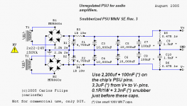
I see you have brought some modifications to your snubberized PSU !
What is the advantage of using some 1R resistors in series with the rest of the PSU ? Doesn't it dramatically decreases the damping factor of the PSU ??
Also, I see you no more use the 100mfd + 100nf on the chip's pins, and came back to the bigger 1500 or 2200mfd.
I currently have 10 panasonic FC caps : is it better to put them all on the PSU board or keep some on the chip's pins ?
Thx for help !
I have a trafo with dual secondaries, unless I would have used a single bridge.
I see you have brought some modifications to your snubberized PSU !
What is the advantage of using some 1R resistors in series with the rest of the PSU ? Doesn't it dramatically decreases the damping factor of the PSU ??
Also, I see you no more use the 100mfd + 100nf on the chip's pins, and came back to the bigger 1500 or 2200mfd.
I currently have 10 panasonic FC caps : is it better to put them all on the PSU board or keep some on the chip's pins ?
Thx for help
!youyoung21147 said:What is the advantage of using some 1R resistors in series with the rest of the PSU ? Doesn't it dramatically decreases the damping factor of the PSU ??
The advantage is lower ripple.
No problems, the resistor is small, and there are big caps after it.
youyoung21147 said:And concerning my PSU would you recommend me to keep some big caps on the chip's pins or put them all on the PSU board ?
Follow the recommendations I've written on my schematic, you won't regret.
It works much better than just small caps near the chip
- Status
- This old topic is closed. If you want to reopen this topic, contact a moderator using the "Report Post" button.