Hang on, I'm wrong on the supply question. He has a split supply and you don't need to do anything about DC. It'll have negligible DC offset. Sorry, I had assumed he was doing a single supply and bridging it. I did mine off a single supply. Actually I have done both but the workhorse was a single supply with some clever stuff included to make it independent of load.
The advantage of running things differentially is huge.
That depends. A fully differential amp should in theory cancel all the even order harmonics. In theory... In reality, such cancellation schemes don't work all that well and some cancellation schemes actually degrade performance. Even if the cancellation scheme does result in a lowering of the even order harmonics, you're left with the odd order harmonics, which many report to sound harsh.
If you want to improve the sound quality of the LM3886, you are far better off using some kind of error correction on it. That's what I do in my Modulus amps. My Modulus-686 is basically a BPA300 with error correction and differential input.
One area where differential signalling is a clear benefit is at line level, especially with longer interconnects. The benefit comes from the common-mode rejection of the differential input, and results in a reduction of hum by several orders of magnitude. It also moves the ground connection out of the signal path, greatly reducing the ground loop issues that seem to plague many DIY builds.
Apart from output impedance, which is again unambitious here with 0R2 resistors balancing the current, there is little to be gained by having 3 LM3886s in parallel except spreading the thermal burden - which is valuable and makes for some of the worst parts of the failings. But a single 3886 can deliver 11A, which is far more than any average speaker can manage.
0.2/3 = 67 mΩ output impedance. While improvements can be made, it's really not bad. I do question whether the 0.2 Ω resistors will survive constant operation with a sine wave, though. Significant power is dissipated in those resistors if the amp is driven to clipping.
Running multiple LM3886es in parallel does reduce the THD as each LM3886 sees a fraction of the load impedance. The improvement is relatively small but definitely measurable.
If you can send the amp a proper differential signal, ie. one the inverse of the other (not that it matters from the point of CMRR) you will find it is a class above what you get from a single ended signal and all the trouble around finding a true ground. When I did that for the first time about 7 years ago, it was the biggest single improvement I had ever heard on any amplifier.
That I definitely agree with. That's why all my amps have differential inputs.
Tom
I don't think we disagree on much there, Tom. Error correction or some form of additional gain and feedback is a must. I do mine a little bit differently in that I drive each 3886 differentially. This stems from doing a single supply version some years ago, unbridged, and it lent itself to getting the DC blocking capacitor out of the direct signal path.
Going back earlier in the amps the same differential topology is used on the inputs. That goes to an active volume control (with a parallel fixed resistor to save on crackle a year down the line), and thence to a LP filter. The output of that LPF is then inverted and those two op amps drive the inputs of the 3886. You can then drop your gain to x12 and get a bit more bandwidth from the amp, while not having lost overall gain.
For some reason the amp went about two years with the socket for that inverter left empty, with the other input being picked up from the local ground, but with the 3886 still in the differential topology. Once that side was powered it was night and day. I don't think I ever bothered to measure it after doing that, but the distortion figures were already about half of the datasheet.
Regarding those 0R2 resistors (which I would anyway try and get down in value precisely because of the power dissipated) I think a proper amp should really parallel them up. I used to like the little Dale resistors for this purpose. Low TCR and low inductance. 3 of the 3W ones or two of the 5W.
BTW, I assume you are taking the feedback after these resistors so they shouldn't contribute to your output impedance. And if you are error correcting then you output impedance should be zero, or thereabouts.
BTW, I assume you are taking the feedback after these resistors so they shouldn't contribute to your output impedance. And if you are error correcting then you output impedance should be zero, or thereabouts.
Hi all,
I am soldering the BPA300 GC - 300W 6x LM3886 circuit board but I have (not yet) all the knowledge about this:
I bought these half finished so the soldering work is not a very great job to do.
The only device I have is a good but simple Multimeter
I have three trimmers on board but I do not know how ( I am very uncertain about this) to set the trimmers the DC offset at about the same level
What DC level mV do I have to set?
From which point to which point can I measure and adjust this with the Multimeter?
Maybe there is something here find on this site this DC setting? I search for this but I cannot find the right answers.
With regards,
Frits
What is the exact out put power of this amp with 8 ohms load?
150 watts rms
Dear people,
Sorry people but I have to come back to it again.
It must be the language barrier, I thought I understood the answer, but now that I look at the circuit itself I don't understand it well enough. I want to connect the circuit and set the DC offset. I still don't know how much mV DC voltage I have to set the variable resistor R4 R12 R17. But even worse, I don't quite understand where to measure. If I understand, resistance R7 R9 R14 that is close to the leg 3 of the LM3886 must measure the minus pole of the input with the red pin of the multimeter and with the black pin of the multimeter. And then set the DC with the variable resistor to an unknown X value?
Awaiting a response, Kind regards, Frits
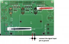
To measure DC offset, connect the signal input pin of the PCB to ground and power it up, as shown in the figure below. Then, you need to measure the output pin of each chip (pin3 that is connect to input of the 0.2ohm 2W resistor), so you will get the same value for all lm3886's. When you turn the pot of one lm3886, DC offset of the two othres chips will change. You need all of them with same DC offset.
Attachments
Hi,
Thanks for all this helpful advice! It maybe a very very stupid question but I am afraid to make shortcut. Unfortunately I still miss the experience and am just very uncertain. And try/error is not so funny for the wallet. I do not understand where to go from this point: "the signal input pin of the PCB to ground....." Do I connect the positive AND the negative input together on a ground point?
It does not matter wich ground point on the PCB. With regards, Frits
Hi all,
Thanks for help me out the fine tuning...
This morning I had the courage to power on one finished amplifier... I Get the DC offset now exact stable on 14mV on all the three points. But not lower than this I cannot fixed for all the three. I hope this is good enough.
With regards,
Frits
Thanks for help me out the fine tuning...
This morning I had the courage to power on one finished amplifier... I Get the DC offset now exact stable on 14mV on all the three points. But not lower than this I cannot fixed for all the three. I hope this is good enough.
With regards,
Frits
An externally hosted image should be here but it was not working when we last tested it.
- Home
- Amplifiers
- Chip Amps
- BPA300 mono block finished and measured