Well, for the past month I have been helping my friend gather parts and assemble Brians 4780 Kit. He snagged a 500 VA +-25V torrid, binding posts. This past week we had enough time to solder her up and try it out. We tested the rectifiers to see if we were getting DC, that was a go the DC for both bridges were putting out around 36V off by a few .01V. Then connected the Chips, and powered up, upon switching on, heard loud sparks cracking sound, killed power.
We thought it was that the chip wasn't insulated, and so we pulled them away from the aluminum case, tried it again, same thing this time we blew some of the pins off. Looking at the pins looks like the V+ didn't quite agree with it.
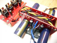
Here are some pics
Not really sure how we messed this up, but we double checked the voltages and what not.
We thought it was that the chip wasn't insulated, and so we pulled them away from the aluminum case, tried it again, same thing this time we blew some of the pins off. Looking at the pins looks like the V+ didn't quite agree with it.
Here are some pics
An externally hosted image should be here but it was not working when we last tested it.
An externally hosted image should be here but it was not working when we last tested it.
An externally hosted image should be here but it was not working when we last tested it.
Not really sure how we messed this up, but we double checked the voltages and what not.
G4ME said:Well, for the past month I have been helping my friend gather parts and assemble Brians 4780 Kit. He snagged a 500 VA +-25V torrid, binding posts. This past week we had enough time to solder her up and try it out. We tested the rectifiers to see if we were getting DC, that was a go the DC for both bridges were putting out around 36V off by a few .01V. Then connected the Chips, and powered up, upon switching on, heard loud sparks cracking sound, killed power.
We thought it was that the chip wasn't insulated, and so we pulled them away from the aluminum case, tried it again, same thing this time we blew some of the pins off. Looking at the pins looks like the V+ didn't quite agree with it.
Here are some pics
.. pics ...
Not really sure how we messed this up, but we double checked the voltages and what not.
I am sorry to hear about your troubles with the amp. Drop me an e-mail if you need any replacement parts.
--
Brian
G4ME said:anyone have any ideas at what i did wrong.
Maby you connected the PSU wires wrong.
Maby you had positive voltage where there should be negative?
Can't see another reason...

That's all I can think of. There are no diodes to get wrong, other than in the bridge, but you said that was cool.
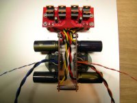
Here's a pic of one I built last night. It is working fine. Compare your wiring to mine. In this pic, yellow and black twisted are V-, red and black twisted are V+.
Here's a pic of one I built last night. It is working fine. Compare your wiring to mine. In this pic, yellow and black twisted are V-, red and black twisted are V+.
Attachments
Any chance that you forgot to shield the speakerposts?Also the RCA's arn't really shielded from the case.

Just to be sure:
* You had the chip mounted to the chassis with no insulation.
* You had no insulation on the RCA's.
Already asked - hopefully the output was fully isolated?
IIRC (can't find it in the datasheet right now) the chip plate is connected to V- which means you had V- shorted directly to earth. I think.
C
* You had the chip mounted to the chassis with no insulation.
* You had no insulation on the RCA's.
Already asked - hopefully the output was fully isolated?
IIRC (can't find it in the datasheet right now) the chip plate is connected to V- which means you had V- shorted directly to earth. I think.
C
I would agree that you problem is that since you had your 4780 attached directly to the case, if the case was grounded you got a nasty short to ground which will fry it in nothing flat. I killed a set of LM4780s that way.
The moral of the story is always isolate LM4780s unless you are sure your heatsink is either completely isolated to all but V-. I always isolate them period.
BTW mine looked exactly the same when they went, it like bad deja vu. Sorry.
The moral of the story is always isolate LM4780s unless you are sure your heatsink is either completely isolated to all but V-. I always isolate them period.
BTW mine looked exactly the same when they went, it like bad deja vu. Sorry.

kmj said:
Any chance that you forgot to shield the speakerposts?
well, i don't have pics of it but my friend just drilled holes for the binding posts just big enough for the lead to go through, so yeah the outputs were shorted.
He is in the process of desoldering and soldering them back up.
An externally hosted image should be here but it was not working when we last tested it.
Shorted! That's the word. Couldn't remember so i went for "shielded". Anyway, if there are fuses they should have blown like crasyaren't the spk outputs shorted in the above pic?
Anyway, put some insulation between the posts and chassi.
- Status
- This old topic is closed. If you want to reopen this topic, contact a moderator using the "Report Post" button.
- Home
- Amplifiers
- Chip Amps
- Ohhh Fire works (4780 Brian GT Kit)