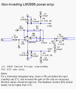
Basically, you should once and for all forget the datasheet circuit.
There are advantages in using very low value resistors, and also with (consistently) manageable DC-Offset, so that the Ci cap can be discarded.
It works, it's simple, it sounds very good.
Even without matching impedances (because I use very low values, and the amp would need a buffer), DC-offset is around 30mv.
Also, regarding the use as a minimalist integrated amp, there's a very important point that it seems few care about: using a (good) input coupling cap after the pot, DC-offset will not change at all depending on the position of the pot.
This is the way to go:
Attachments
what is the point of the resistors in series with the output? was one of them supposed to be an inductor instead?
And what is the point of shielding the output from the amp-chip? is that to reduce interference that it might contaminate the input with?
WHy not add a capacitor to the mute pin to give a delay to the turn-on (to remove any possible thumping, especially if part of an integrated amp, when the preamp might not have stabilized yet).
depeding upon the preamp being used in an integrated amplifier, the coupling cap from the wiper of the pot to the amplifier input would not be needed. I would just remove the input resistor to ground and the input capacitor and connect the + input directly to the wiper of the pot, making sure that there will be no DC on the pot. If the pot is driven by a typical transistor/FET stage, the coupling capacitor from the stage to the top of the pot should take care of the DC. IF driven by op-amps, there should be a coupling capacitor in the amp somewhere to take it off. adding a capacitor to the feedback network to bring the gain down to unity at DC is also helpful, too.
I think the zobels snubbing the power supply raisl wouldn't be needed. I would install some smallish film capacitors right at the pins of the IC, though.
Dr. Photon said:I would just remove the input resistor to ground and the input capacitor and connect the + input directly to the wiper of the pot, making sure that there will be no DC on the pot. If the pot is driven by a typical transistor/FET stage, the coupling capacitor from the stage to the top of the pot should take care of the DC. IF driven by op-amps, there should be a coupling capacitor in the amp somewhere to take it off. adding a capacitor to the feedback network to bring the gain down to unity at DC is also helpful, too.
I think the zobels snubbing the power supply raisl wouldn't be needed. I would install some smallish film capacitors right at the pins of the IC, though.
You absolutely need the res. to GND in case the pot (with time and depending on its quality) decides not to conduct. You'll get a nice rail DC on the speakers or as a min. nasty cracking (DC/ spikes).
The res in the output are in addition to the RC network and improve the stability of the amp in case the impedance of your cables/speakers have high capacitance component.
I'm 100% convinced that you need the snubbers on the PS pins. It made a huge diff. on my amp. Just the smallish caps wont do anything (personally tried it on my GC). How much difference it'll make depends on the type of the PS caps and how revealing your speakers are.
Greg
carlosfm said:Basically, you should once and for all forget the datasheet circuit.
There are advantages in using very low value resistors, and also with (consistently) manageable DC-Offset, so that the Ci cap can be discarded.
It works, it's simple, it sounds very good.
Even without matching impedances (because I use very low values, and the amp would need a buffer), DC-offset is around 30mv.
Also, regarding the use as a minimalist integrated amp, there's a very important point that it seems few care about: using a (good) input coupling cap after the pot, DC-offset will not change at all depending on the position of the pot.
This is the way to go:
Carlos,
The only worry I have is the DC offset. I went the same course at one point and got offset more than 65-70mV, so had to increase the res. to GND. It would be OK if no input cap is used, so that at moderate volume levels the DC offset is fairly low. But I wanted to not have DC going through the pot (noise issue) and not to depend on the pot for the DC offset. With low out impedance preamp that kind of configuration will rock... Of course servo would solve the DC offset too, but I have never tried it and no time for now.
I tried the T-network, which actually does exact opposite (increases the ser res. to -IN) and to be honest didn't like the sound too much. It created a bump in the highest frequencies. My speakers are quite revealing and didn't sound as open as the low -in res. classic version. Also I found it's good to connect the FB res from -In to GND to the same star GND where the speaker is connected. The +in to GND res should also go there. And the input GND should go to the same GND-star. The lower the res. values of the NFB the more important that becomes.
Nice work!
Greg
I'll give it a go Carlos.
My 'findings' to date are that I prefer the single feedback resistor to the T-network and I prefer the inverting circuit to the non-inverted.
It may not be obvious to newbies but we should add that this circuit would be used with the snubbered PSU.
I'll be ordrering parts today (so if you have any more ideas please post them before noon )!
)! ")
My 'findings' to date are that I prefer the single feedback resistor to the T-network and I prefer the inverting circuit to the non-inverted.
It may not be obvious to newbies but we should add that this circuit would be used with the snubbered PSU.
I'll be ordrering parts today (so if you have any more ideas please post them before noon
)! It's no harm to have it in mind though.carlosfm said:Basically, you should once and for all forget the datasheet circuit.
Carlos, if you _do_ read the datasheet you'll realize that your claim isn't right. If you are unlucky you may get a LM3886 with 10 mV and that gives you 300 mV offset regardless of resistor values.carlosfm said:It works, it's simple, it sounds very good.
Even without matching impedances (because I use very low values, and the amp would need a buffer), DC-offset is around 30mv.
Once again: C2, C3 and C4, C5 does form a parallel resonance circiut so you should get rid of C3 and C5. Why don't you use _only_ C2 tight together with C7+R4?
The IC have it's return currents to ground so I'll suspect that C6 doesn't do much good but not harm either.
Why don't you use mute, pretty convinient and has no drawbacks.
What is the advantage of using 0.25 ohms as output impedance compared to have much lower (using an inductor)?
Nuuk said:I'll be ordrering parts today (so if you have any more ideas please post them before noon
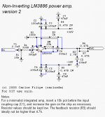
Still before noon.
Sorry, on my yesterday late schematicing
I forgot to include two components on the input.Here's the revised schematic.
Attachments
Here comes the Gang
Notice that I'm not claiming.
30mv is what I have on this working amp, that is
 in-in on my main system right now.
Also, if you change R1 (15k) for a 10k resistor, DC-offset will be a little lower, at around 25mv.
I used 15k because I had some good 2.2uf caps I wanted to use.
I wouldn't say that, but you are free to sell your fish.
Yes, because of the PSU.
peranders said:Carlos, if you _do_ read the datasheet you'll realize that your claim isn't right. If you are unlucky you may get a LM3886 with 10 mV and that gives you 300 mV offset regardless of resistor values.
Notice that I'm not claiming.
30mv is what I have on this working amp, that is
in-in on my main system right now.Also, if you change R1 (15k) for a 10k resistor, DC-offset will be a little lower, at around 25mv.
I used 15k because I had some good 2.2uf caps I wanted to use.
Upupa Epops said:All, what Carlos " develope " now, you can find on my PA 03 ( and my version is still better ).
I wouldn't say that, but you are free to sell your fish.
Upupa Epops said:Not a long time ago, Carlos had said about my version, that it is s...
Yes, because of the PSU.
Some explaning
As I say on the schematic, this is a power amp.
And for that role, it doesn't need an input buffer.
What it does need is a good active pre.
Notice that I give the option for a "minimalist integrated amp", which is just using a pot and increasing the gain of the amp.
I thought I should mention this option, even if it's not my favourite.
For an integrated amp I would use a gainstage at 2~3x gain and keep the gain on the LM3886 the same.
This is the way to go.
I have a preamp, with a gain of 3x.
This NI power amp doesn't need an input buffer if it's used as a power amp.
Even as a power amp, with the Inverting topology, it is recommended (and beneficial) to use an input buffer.
So, in conclusion, using the chip as a dedicated power amp as I do, I'm having very good results with this amp (exactly as on the schematic), better than what I tested before with the NI topology and the commonly used values.
peranders said:Why don't you use mute, pretty convinient and has no drawbacks.
Aha!
At last a good question.
I just use a 10k resistor to the negative rail, never used the cap.
And there's absolutely no turn-on thump, with the high cap. snubberized PSU.
Why don't I use the cap on the muting circuit?
I don't feel very well inserting more capacitance on the negative rail, even it it's after a 10k resistor.
Maby it's just me, but I don't do that.
Carlos,
You know, I've been looking at the 0.27 Ohm res at the output for so long and never actually implemented it until now (didn't believe it would make a big diff.). So, looking at your schematic I decided to connect it today. I used an ugly ceramic 5W resistor because it has some extra inductance and I think it's perfect for that place. Well, It did improve the HF. It looks like the amp has had some slight instability problem and that resistor made it sound more balanced, not as forward in the HF area. I did have the Zobel network before, but I guess it's not enough in some cases. Now I have to revisit some other variations of GC including the t-network (the advantage of much lower DC offset). One never knows....
Greg
I used an ugly ceramic 5W resistor because it has some extra inductance and I think it's perfect for that place. Well, It did improve the HF.
Well, I've done the same thing. Also put some 0R22 ugly ceramics (5W) and I think that sound in HF changed somehow, but will know more after few days/weeks.
BTW, just finished snubber this weekend, had no chance to implement it yet. I have listened it while I was working. LM3875 NI was connected to my mini monitors in workshop (Visonik David) and there were certainly difference in sound between my 338 reg PSU and snubber. Will try next week on main system.
Hi
Carlos, your Gc now gets me thinking into more options, as:
1. Use it with a Bride of Zen preamp, it should be more than enough,
2. Try to use a tube, but not only as a buffer, but also with some gain??
3. Since 0,22 ohm resistor has been added , maybe Zobel can be removed.
If I am not mistaken, Peter Daniel does not use a Zobel...
Regards
Vix
Carlos:
Have you experimented with the output resistor value? Or more specifically, why ~0R22?
I am still gathering parts for that SUSY amp but you now have me pondering component values again. Fortunately, a good selection of the small wattage resistors in various values is cheap relative to the other parts so I can easily afford to experiment. The larger output resistors are a tad more, so I'm curious. Since my amp will use the LM4780 with the amps paralleled I already had plans for 0R1.
And, of course, I have to know - how do you think this compares to the inverted amp?
C
Have you experimented with the output resistor value? Or more specifically, why ~0R22?
I am still gathering parts for that SUSY amp but you now have me pondering component values again.
Fortunately, a good selection of the small wattage resistors in various values is cheap relative to the other parts so I can easily afford to experiment. The larger output resistors are a tad more, so I'm curious. Since my amp will use the LM4780 with the amps paralleled I already had plans for 0R1. And, of course, I have to know - how do you think this compares to the inverted amp?
C
cjd said:Have you experimented with the output resistor value? Or more specifically, why ~0R22?
I didn't test 0.1R, but it seems very small to have any effect.
A resistor in series with the output, as with any op-amp, makes the chip stable driving capacitive loads.
The amp is much less picky with cables.
cjd said:And, of course, I have to know - how do you think this compares to the inverted amp?
Right now the only inverted LM3886 I have has a regulated LM338 PSU.
The non-inverted, non-buffered LM3886 as per this schematic is sounding better, but the PSU is also different, so I can't make a direct comparison.
- Status
- This old topic is closed. If you want to reopen this topic, contact a moderator using the "Report Post" button.
- Home
- Amplifiers
- Chip Amps
- Improving the Non-Inverting chipamp