I need to make a high-power amp, and I thought that the LM3886 would do the job. My power supply is +/- 42.5v at no load. The speaker that I want to drive has two 5.4 ohm voice coils. I was thinking about making 2 bridge/parallel amps, one for each coil. After doing some calculations I figured out that the amp would need to dissipate ~550-600 watts max. With 16 chips for the whole amp, each chip would need to dissipate ~35w.
Would it be better to use 8 chips per bridge/parallel setup (16 chips for the amp) or paralleled output transistors?
Would paralleling 4 chips work, or is it too many chips?
Would it be better to use 8 chips per bridge/parallel setup (16 chips for the amp) or paralleled output transistors?
Would paralleling 4 chips work, or is it too many chips?
xplod1236 said:I need to make a high-power amp, and I thought that the LM3886 would do the job. My power supply is +/- 42.5v at no load. The speaker that I want to drive has two 5.4 ohm voice coils. I was thinking about making 2 bridge/parallel amps, one for each coil. After doing some calculations I figured out that the amp would need to dissipate ~550-600 watts max. With 16 chips for the whole amp, each chip would need to dissipate ~35w.
Would it be better to use 8 chips per bridge/parallel setup (16 chips for the amp) or paralleled output transistors?
Would paralleling 4 chips work, or is it too many chips?
Power supply is to high, particularly for bridging.
IMO you have two choices:
1) Regulate the voltage to aorund +/-30v, then parallel/bridge.
2) Use another chip as first stage and boost the output.
Carlos
Re: Re: 16 paralleled LM3886s or output transistors?
This is the only transformer that I have that is suitable for the chips. I know that the voltage is a little high, but wouldn't it decrease under load?
1) I want to keep this amp simple. Wouldnt the chips handle 40v and 4 amps each? Each chip would see a load of 10.8 ohms. I have a lot of LM3886s, and I would like to use them.
2) See 1
This is the only transformer that I have that is suitable for the chips. I know that the voltage is a little high, but wouldn't it decrease under load?
carlmart said:
IMO you have two choices:
1) Regulate the voltage to aorund +/-30v, then parallel/bridge.
2) Use another chip as first stage and boost the output.
Carlos
1) I want to keep this amp simple. Wouldnt the chips handle 40v and 4 amps each? Each chip would see a load of 10.8 ohms. I have a lot of LM3886s, and I would like to use them.
2) See 1
Do it man, forget the nay-sayers.
If you did a bridge-parallel arrangement with 4 paralleled chips bridged with another 4 paralleled (per voice coil), then each chip 'sees' an effective load of 10.4 Ohms (2x the real voice coil impedance). With a +-42 V supply, 10.4 ohms is OK; it is within the Safe Operating Area specified in the datasheet, and that's what matters. I also estimate about 35 W power dissipation (per chip) based on the data sheet, confirming your own observation.
I strongly recommend, no, absolutely insist, that you use the LM3886T, not the LM3886TF. The latter has too much die-to-case thermal resistance and will overheat internally when put under the kind of stresses to which you will be subjecting the device.
I don't know what kind of transformer your are planning to use, but it had better be huge. I think about 1500 VA sounds about right.
One other thing, carefully read and understand AN-1192: Application Note 1192 Overture™ Series High Power Solutions. You must make sure that the gain of all paralleled chip amps is matched very closely, and you must make sure that DC offset of each is minimal or, better yet, zero. You may need to use DC servos to achieve this. These steps will be of great help in reducing the power dissipation of the amplifier, both at idle and operating.
I strongly recommend, no, absolutely insist, that you use the LM3886T, not the LM3886TF. The latter has too much die-to-case thermal resistance and will overheat internally when put under the kind of stresses to which you will be subjecting the device.
I would use the T version, but I already have 16 of the insulated ones, so I will use those. If they fry, then I'll switch to the non-insulated ones.
I don't know what kind of transformer your are planning to use, but it had better be huge. I think about 1500 VA sounds about right.
The transformer is coming from a Fisher stereo receiver. I don't know the rating of it, but it looks pretty beefy. The fuses on the secondaries were 6A. I don't really care how much power I will get out of it. That's the only transformer that I have that will work with the chips. Another one I have is 35-0-35 and another is 52-0-55 vac, both of which would fry the chips.
One other thing, carefully read and understand AN-1192: Application Note 1192 Overture™ Series High Power Solutions. You must make sure that the gain of all paralleled chip amps is matched very closely
I did read it a few times already. All the chips will be non-inverting, with a drv134 in front to split up and invert 1/2 of the signal.
Can I NOT use a cap between gnd and the resistor that goes to the inverting in?
Konnichiwa,
That is 85V between the PSU Pin's. The LM3886 is rated as 94V max, so you can JUST ABOUT get away with it, but I would recommend finding a way to reduce the Voltage slightly. If your mains transformer is a torroidal type you can wind by had a few doxend turns as "buck" winding for the primary, thus reducing the PSU Volate.
Alternatively using "amplified capacitor" circuits with a PSU "Clamp" at +/-40V would also work well.
Sounds doable allright.
Pro LM3886 is that they are next to indestructable if applied with minimal care. The same cannot be said of normal output transistors in discrete amplifiers, at least at the kind of supply voltages and currents involved.
Depends, for music only I suspect you could get away with 2-3 parallel chips. If you want to do sine wave testing near clipping you need to worry not just about peak currents but also dissipation, suggesting the need for more IC's. On the positive side, all that will happen if you do thermally overtax the system is that whole amp will rapidly shut down with the LM3886, with discrete output transistors thermal runaway tends to be a lot more catastrophic.
Sayonara
xplod1236 said:My power supply is +/- 42.5v at no load.
That is 85V between the PSU Pin's. The LM3886 is rated as 94V max, so you can JUST ABOUT get away with it, but I would recommend finding a way to reduce the Voltage slightly. If your mains transformer is a torroidal type you can wind by had a few doxend turns as "buck" winding for the primary, thus reducing the PSU Volate.
Alternatively using "amplified capacitor" circuits with a PSU "Clamp" at +/-40V would also work well.
xplod1236 said:The speaker that I want to drive has two 5.4 ohm voice coils. I was thinking about making 2 bridge/parallel amps, one for each coil. After doing some calculations I figured out that the amp would need to dissipate ~550-600 watts max. With 16 chips for the whole amp, each chip would need to dissipate ~35w.
Sounds doable allright.
xplod1236 said:Would it be better to use 8 chips per bridge/parallel setup (16 chips for the amp) or paralleled output transistors?
Pro LM3886 is that they are next to indestructable if applied with minimal care. The same cannot be said of normal output transistors in discrete amplifiers, at least at the kind of supply voltages and currents involved.
xplod1236 said:Would paralleling 4 chips work, or is it too many chips?
Depends, for music only I suspect you could get away with 2-3 parallel chips. If you want to do sine wave testing near clipping you need to worry not just about peak currents but also dissipation, suggesting the need for more IC's. On the positive side, all that will happen if you do thermally overtax the system is that whole amp will rapidly shut down with the LM3886, with discrete output transistors thermal runaway tends to be a lot more catastrophic.
Sayonara
It is certainly true that real music is very different than sinewave testbench signals. Keep in mind that average power dissipation isn't the only important thing, instantaneous current is also important. The SPiKe protection may kick in if the instantaneous current shoots too high, even if the chips are kept cool.I suspect you could get away with 2-3 parallel chips. If you want to do sine wave testing near clipping you need to worry not just about peak currents but also dissipation, suggesting the need for more IC's.
He could get away with just 3 chips per parallel arrangement, which would still keep the effective load for each chip at 8.1 ohms or so. That would be acceptable, but is approaching the edge of the safe area. Since xplod wants to use TF devices, I would still recommend using 4 chips in parallel. This will help distribute the power dissipation amoung more devices, reducing the chances of overheating (which can be a real concern with the TFs).
Well, with 42 V after rectification your secondaries are 30 V each. 30 V(rms) * 6 A(rms) is 180 VA, per secondary. So, it is an approximately 360 VA transformer. You can also check out the specs on the back panel of the receiver it came out of to see its line rating (usually in Watts in the USA; but VA in Canada). Luckily, real-world music does not demand high continuous power. Most transformers can deliver a lot more than their rated power for short bursts, as long as the average power is low enough that the transformer doesn't overheat.The transformer is coming from a Fisher stereo receiver. I don't know the rating of it, but it looks pretty beefy. The fuses on the secondaries were 6A
macboy said:
Well, with 42 V after rectification your secondaries are 30 V each. 30 V(rms) * 6 A(rms) is 180 VA, per secondary. So, it is an approximately 360 VA transformer. You can also check out the specs on the back panel of the receiver it came out of to see its line rating (usually in Watts in the USA; but VA in Canada).
It says 230W max, but the fuse on the power line to the transformer is 5A.
What about this idea--bootstrapping?
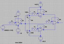
Too much explaining, so just look at the attached schematic. The first opamp is a regular opamp, and the 3 on the right are LM3886s. I would add output transistors to share the current and the heat. I can switch the power supply to +/- 50v.
Would this work?
Too much explaining, so just look at the attached schematic. The first opamp is a regular opamp, and the 3 on the right are LM3886s. I would add output transistors to share the current and the heat. I can switch the power supply to +/- 50v.
Would this work?
Attachments
johngalt47 said:On a slightly different note [yes, I realize that is a pun], wouldn't using multiple chips kind of mess up the sound a little?
None of the chips and ancilliary components will be exactly alike, right? Or would the differences be so small as to be undetectable?
He just wanna go gaga with all those extra chips he has... let it be ;-)
Go on man do what you wanna, half the fun is trying new things... be a yEAH sayer.

Seriously I think you should take a look at Lars Clausens' ZETA amp which is under development now.xplod1236 said:I need to make a high-power amp, and I thought that the LM3886 would do the job. My power supply is +/- 42.5v at no load. The speaker that I want to drive has two 5.4 ohm voice coils. I was thinking about making 2 bridge/parallel amps, one for each coil. After doing some calculations I figured out that the amp would need to dissipate ~550-600 watts max. With 16 chips for the whole amp, each chip would need to dissipate ~35w.
Would it be better to use 8 chips per bridge/parallel setup (16 chips for the amp) or paralleled output transistors?
Would paralleling 4 chips work, or is it too many chips?
You have a couple of problems and the main problem is max voltage of the LM3886 and also the cooling of the same. With Lars' design you are not limited by the max supply voltage.
Konnichiwa,
To put it simple, if you want a simple to build amplifer that is fully protected by design, use the LM3886 in bridge/parallel however many you need/want to use.
Once you go for bootstrapping, extra current or current/voltage booster Transistors etc you start loosing most if not all of the advantages.
And look at it that way, that approach (Bridge/Parallal 3886) to making Amp's is good enough for Jeff Rowland...
Sayonara

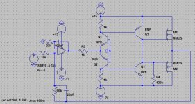
With my new design, I'm using a +/- 75v supply. The transformer comes form a 250w max 2 channel at 8-16 ohm amp, which powered two 2.7 ohm subs. I got +/-45 vrms per channel out of it, meaning that it supplied 3kw of power. It put out a lot of heat, but it worked. I'm going to run one 2.7 ohm sub from it, and I think that it will be fine. I know that I am losing the protection from the chips, but I will implement something similar. Now to my question: which output MOSFETs would be good for this application?
- Status
- This old topic is closed. If you want to reopen this topic, contact a moderator using the "Report Post" button.
- Home
- Amplifiers
- Chip Amps
- 16 paralleled LM3886s or output transistors?