Hello,
I have been making a 100W amp using the parallel circuit in the Overture Series High Power Solutions application notes and fired it up for the first time last night. It worked first time and everything is fine apart from some crackling that I am putting down to a bad RCA connection and the fact that it heats up to about 80 degrees C in about 30 seconds I have a feeling it could be due to some high frequency oscillations, since there was no audible noise.
So my question is how do I test for these? And I have access to a CRO and signal generator.
Cheers
Jye
I have been making a 100W amp using the parallel circuit in the Overture Series High Power Solutions application notes and fired it up for the first time last night. It worked first time and everything is fine apart from some crackling that I am putting down to a bad RCA connection and the fact that it heats up to about 80 degrees C in about 30 seconds
I have a feeling it could be due to some high frequency oscillations, since there was no audible noise.So my question is how do I test for these? And I have access to a CRO and signal generator.
Cheers
Jye
Attachments
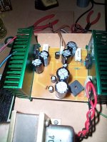
one thing about the heat-sink you picture == they are one heck of a lot LESS efficient than one in which the fins are not "interrupted" -- and if you aren't using a fan the C/W rating is much less than you would suspect.
you can see the oscillation on an oscilloscope -- it helps if you have a scope with FFT -- then you can peg the frequency in a couple seconds -- if it is oscillating make sure that the lead lengths are as short as possible (tack the resistors directly to the chip pins), incorpoate the 0.7uH choke which National recommends, make sure that the filter caps on the power supply pins are bypassed with 100nF mylars. Bypass capacitors as seem to be shown in your photo (being several mm from the supply pins on the amp chip) are about as useful as teats on a bull.
you can see the oscillation on an oscilloscope -- it helps if you have a scope with FFT -- then you can peg the frequency in a couple seconds -- if it is oscillating make sure that the lead lengths are as short as possible (tack the resistors directly to the chip pins), incorpoate the 0.7uH choke which National recommends, make sure that the filter caps on the power supply pins are bypassed with 100nF mylars. Bypass capacitors as seem to be shown in your photo (being several mm from the supply pins on the amp chip) are about as useful as teats on a bull.
Thanks Jackinnj,
I have placed some filter caps on the supply pins of the chip but the oscillations are still present. On the scope the oscillations are at about 150kHz and 5vp-p. One thing I did notice is if I turn the power supply down to about +/- 9v the oscillations disappear and all is well
I will try and get some chokes and try that out tomorrow. But in the mean time any other comments are much appreciated.
Cheers
Jye
Hi,
As of the National data sheet, the chip switches off (activates it's undervoltage-protection) at +-9V. This would mean that your oscillations are entirely independent of the supply voltage. Is the output (test/audio) signal still present when the oscillation stops at +-9V?
If not, you already have determined that the oscillation is affected by the protection circuit, which could narrow the suspect components/wires down when looking at the internal block diagram.
Have you tried improved input filtering (series 1kR, parallel 220pF) to rule out any EMI induced swinging? Next would be bypassing the feedback series resistor (e.g. 100pF in parallel upon it).
Hope this helps,
Sebastian.
One thing I did notice is if I turn the power supply down to about +/- 9v the oscillations disappear and all is well
As of the National data sheet, the chip switches off (activates it's undervoltage-protection) at +-9V. This would mean that your oscillations are entirely independent of the supply voltage. Is the output (test/audio) signal still present when the oscillation stops at +-9V?
If not, you already have determined that the oscillation is affected by the protection circuit, which could narrow the suspect components/wires down when looking at the internal block diagram.
Have you tried improved input filtering (series 1kR, parallel 220pF) to rule out any EMI induced swinging? Next would be bypassing the feedback series resistor (e.g. 100pF in parallel upon it).
Hope this helps,
Sebastian.
are you using the 0.7uH choke? You can wind 15 turns of #20 enamelled wire around a 2 watt carbon resistor -- if you don't have magnet wire you can use the regular RS, PVC insulated wire, it just won't look pretty.
you could try placing a 220pF capacitor across the input pins -- but this is mainly to keep Radio Frequency Interference out of the chip.
you could try placing a 220pF capacitor across the input pins -- but this is mainly to keep Radio Frequency Interference out of the chip.
jackinnj said:
you could try placing a 220pF capacitor across the input pins -- but this is mainly to keep Radio Frequency Interference out of the chip.
Not really related to this post, but I can confirm that the 220pF cap across the inputs works a treat if you live next to the regional radio transmitter, like me!
Steve
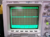
Thanks for all the help guys. I ended up putting a 1nF cap from the input (pin 7) to ground and that cleaned it right up
Finished up with 5.1mV DC offset and I have attached an image of the final output when the input is grounded, the divisions are 100mV and 1us.
Will fire it up tonight and report back with the final verdict
Finished up with 5.1mV DC offset and I have attached an image of the final output when the input is grounded, the divisions are 100mV and 1us.
Will fire it up tonight and report back with the final verdict
Attachments
Jye said:Thanks for all the help guys. I ended up putting a 1nF cap from the input (pin 7) to ground and that cleaned it right up
Hmmm...
Finished up with 5.1mV DC offset and I have attached an image of the final output when the input is grounded, the divisions are 100mV and 1us.
Well, that looks like a waveform to me
With 100mV/div, those occasional 'bursts' are some mV high and at 1us/div they are of high frequency.
I count around 10 zero-crossings per div (us), so we're in the MHz range!
Are you shure you solved the problem, not just reduced it? Or maybe there's more than one problem? Any idea what this is? Or maybe I'm just too tired?
Sebastian.
PS: If the 1nF cap does nothing more than reduce RFI and noise pickup of your scope's measurement tip, then you could probably have had no problem at all!
Hey sek and peranders
The original oscillations were about 150 kHz and 900 mV, putting the cap in removed all of that. The oscillations you can still see are coming from the DC power supply in my lab. I placed some decoupling caps underneath the PCB but they don’t seem to be doing too much, I will replace them and see what happens. I have yet to test it on the CRO with the transformer connected (this weekend)
But after saying all that the thing works, I played it for a couple of hours last night (with the transformer hooked up) and it did not heat up at all with and without a signal (and I drove it hard trying to get it to heat up a bit ). No humming and sometimes a small pop when it is turned on and off due to a second hand on/off switch.
Overall I am pretty happy and will end up using it to drive a sub for a pair of W3-871S.
The original oscillations were about 150 kHz and 900 mV, putting the cap in removed all of that. The oscillations you can still see are coming from the DC power supply in my lab. I placed some decoupling caps underneath the PCB but they don’t seem to be doing too much, I will replace them and see what happens. I have yet to test it on the CRO with the transformer connected (this weekend)
But after saying all that the thing works, I played it for a couple of hours last night (with the transformer hooked up) and it did not heat up at all with and without a signal (and I drove it hard trying to get it to heat up a bit
). No humming and sometimes a small pop when it is turned on and off due to a second hand on/off switch. Overall I am pretty happy and will end up using it to drive a sub for a pair of W3-871S.
- Status
- This old topic is closed. If you want to reopen this topic, contact a moderator using the "Report Post" button.
- Home
- Amplifiers
- Chip Amps
- How to test for oscillations?