Time for a new amp! Some time ago, I started with a project, that got a bit out of hand. In the background, I'm still working on it, but with all the new ideas for that amp, the pile of unused components started growing: chassis, PSU boards + caps, transformer, DAC and volume control. So why not use those parts and make an amplifier out of it? This time keeping it simple.
Chassis:
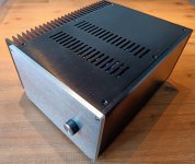
Ebay / AliExpress "2515 Aluminium Amplifier Enclosure"
Inrush limiter:
2x 5 Ohm NTC resistor in series
Nothing fancy, but it works just fine
Transformer:
Amplimo 300VA - 2x22V
Amplimo 15VA - 2x12V (for DAC PSU)
Power Supplies:
Audiosector - RECT-PCB
MUR860 diodes
22.000uF caps + bleeder resistors (just two 8.2kOhm 1/2W resistors in in parallel)
No snubber
Amplifier:
Neurochrome LM3886DR
DAC:
Ebay / AliExpress: CS8416+PCM1794 24bit/192kHz DAC
Volume control:
Valab 23 steps - 20k
Binding posts:
Sourced from Neurochrome
Cabling:
-Whatever was available in the drawer, mostly Lapp / Ölflex cables:
230VAC circuit: 1mm^2 (orange)
22VAC circuit: 1mm^2 (colours same as Amplimo: red, blue, yellow, grey)
DC circuit: 2.5mm^2 (black)
LM3886DR to terminals: 4mm^2 (black/red)
Notes
A. 4mm^2 would have been better for the DC circuits, but with the tight space, the 2.5 offers a bit more flex.
B.
Solder:
60/40, nothing special here
================================================================
Project "points of attention"
Volume control:
The DAC has a 2V RMS output, while the LM3886DR boards have an input sensitivity of 950mV RMS. In other words: the last few steps of the attenuator will drive the LM3886 into clipping. Not the highest priority at the moment.
DAC PSU:
These kits have been circling around for a long time now, "back in the day", the first versions where built with 7805/7812/7912 voltage regulators. Not the best option when it comes to PSRR. A Dutch guy built a LM317/LM337 based PSU, achieving a significant reduction in noise, more details here (in Dutch, with pictures, schematics and measurements): click here
The DAC I bought has LM317/337 regulators, but I haven't reversed engineered the schematics. Depending on how well the newer PSU is done, it might be rewarding to do a PSU upgrade later on in the process.
DAC Opamps:
Default: AD827
Possible upgrade options: LM4562 or LME49720 (click)
Update 05-DEC-2021: LM4562 ordered, on the Dutch forum they are regarded as a good drop-in replacement. The LME49720 had availability issues anyway, and reading trough the referred thread, the internals and performance specs seem to be the same.
DAC mods:
Multiple well known mods are circling around the internet for this DAC. I'm not the type the type that determines improvements by listening, I rather heave measurements (on of the reasons I like Neurochrome so much). Example mods:
Modded Hong Kong DAC
================================================================
Pictures:
Note: something seems to be off with picture size ratio's, all pictures are clickable, showing them with the correct aspect ratio.
Rough estimate for the layout

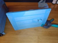
Rear panel, work in progress
-Each toroid will be fused separately
-Power switch is on the rear, two reason: 1. I wanted to keep the front as clean as possible and 2. the chassis is tight, doing it this way avoids running 230VAC cables trough the entire cabinet.

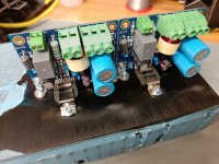
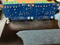
DAC + PSU stack
-With of the boards = same
-Length of PCB = not the same, bummer

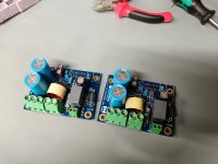
Added 05-DEC-2021 - PSU boards:
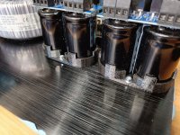
Personal note: they are very, very compact, compliments to that! One of my design ideas was to avoid hardwiring where possible. The spacing on the PCB is standard 5.08mm and lucky me, I had some screw terminals laying around. One setback: the screw terminals do interfere with the diode's. After slightly modifying a screw terminal and raising the diodes a bit, it all fitted.
First soldering all parts on one side, then cleaning the solder joints, then mounting the caps with enough clearance and cleaning again. To be honest: not the most user friendly method. Aside from that, the solder joints become a "stressed" member.
And yes, I know not all diodes look the same. All are MUR860, functionally all the same, only difference is the isolated/non-isolated. Just a mistake while ordering for this project and saved by some diodes laying around for another project.

*picture taken before cleaning PCB topside after soldering the caps in.
Chassis:
Ebay / AliExpress "2515 Aluminium Amplifier Enclosure"
Inrush limiter:
2x 5 Ohm NTC resistor in series
Nothing fancy, but it works just fine
Transformer:
Amplimo 300VA - 2x22V
Amplimo 15VA - 2x12V (for DAC PSU)
Power Supplies:
Audiosector - RECT-PCB
MUR860 diodes
22.000uF caps + bleeder resistors (just two 8.2kOhm 1/2W resistors in in parallel)
No snubber
Amplifier:
Neurochrome LM3886DR
DAC:
Ebay / AliExpress: CS8416+PCM1794 24bit/192kHz DAC
Volume control:
Valab 23 steps - 20k
Binding posts:
Sourced from Neurochrome
Cabling:
-Whatever was available in the drawer, mostly Lapp / Ölflex cables:
230VAC circuit: 1mm^2 (orange)
22VAC circuit: 1mm^2 (colours same as Amplimo: red, blue, yellow, grey)
DC circuit: 2.5mm^2 (black)
LM3886DR to terminals: 4mm^2 (black/red)
Notes
A. 4mm^2 would have been better for the DC circuits, but with the tight space, the 2.5 offers a bit more flex.
B.
Solder:
60/40, nothing special here
================================================================
Project "points of attention"
Volume control:
The DAC has a 2V RMS output, while the LM3886DR boards have an input sensitivity of 950mV RMS. In other words: the last few steps of the attenuator will drive the LM3886 into clipping. Not the highest priority at the moment.
DAC PSU:
These kits have been circling around for a long time now, "back in the day", the first versions where built with 7805/7812/7912 voltage regulators. Not the best option when it comes to PSRR. A Dutch guy built a LM317/LM337 based PSU, achieving a significant reduction in noise, more details here (in Dutch, with pictures, schematics and measurements): click here
The DAC I bought has LM317/337 regulators, but I haven't reversed engineered the schematics. Depending on how well the newer PSU is done, it might be rewarding to do a PSU upgrade later on in the process.
DAC Opamps:
Default: AD827
Possible upgrade options: LM4562 or LME49720 (click)
Update 05-DEC-2021: LM4562 ordered, on the Dutch forum they are regarded as a good drop-in replacement. The LME49720 had availability issues anyway, and reading trough the referred thread, the internals and performance specs seem to be the same.
DAC mods:
Multiple well known mods are circling around the internet for this DAC. I'm not the type the type that determines improvements by listening, I rather heave measurements (on of the reasons I like Neurochrome so much). Example mods:
Modded Hong Kong DAC
================================================================
Pictures:
Note: something seems to be off with picture size ratio's, all pictures are clickable, showing them with the correct aspect ratio.
Rough estimate for the layout
Rear panel, work in progress
-Each toroid will be fused separately
-Power switch is on the rear, two reason: 1. I wanted to keep the front as clean as possible and 2. the chassis is tight, doing it this way avoids running 230VAC cables trough the entire cabinet.
DAC + PSU stack
-With of the boards = same
-Length of PCB = not the same, bummer
Added 05-DEC-2021 - PSU boards:
Personal note: they are very, very compact, compliments to that! One of my design ideas was to avoid hardwiring where possible. The spacing on the PCB is standard 5.08mm and lucky me, I had some screw terminals laying around. One setback: the screw terminals do interfere with the diode's. After slightly modifying a screw terminal and raising the diodes a bit, it all fitted.
First soldering all parts on one side, then cleaning the solder joints, then mounting the caps with enough clearance and cleaning again. To be honest: not the most user friendly method. Aside from that, the solder joints become a "stressed" member.
And yes, I know not all diodes look the same. All are MUR860, functionally all the same, only difference is the isolated/non-isolated. Just a mistake while ordering for this project and saved by some diodes laying around for another project.
*picture taken before cleaning PCB topside after soldering the caps in.
Last edited:
Looks like a nice and compact build. Fun project!
What a bummer with the PCB stack-up. Since you're using two stacked standoffs I wonder if you could make a little bracket to go where the two standoffs are joined. This bracket would scoot things over enough that you can mount the top board properly. Alternatively, if you have room, just add a mezzanine plate on top and mount the top board to it.
Tom
@tomchr
You are right, a proper adapter would be the best option.
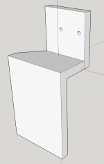
Step 1:
3D drawing in Sketchup. The holes are drawn at a 1.0mm diameter, giving me enough "flesh" to drill them out later and thread an M3 in there.

Step 2:
Play around with the 3D printer. In all honesty, I rarely print parts this small, so it took two runs, before a workable part exited the printer.

Step 3:
Installation (at a later moment)
You are right, a proper adapter would be the best option.
Step 1:
3D drawing in Sketchup. The holes are drawn at a 1.0mm diameter, giving me enough "flesh" to drill them out later and thread an M3 in there.
Step 2:
Play around with the 3D printer. In all honesty, I rarely print parts this small, so it took two runs, before a workable part exited the printer.
Step 3:
Installation (at a later moment)


A picture says more than a thousand words....

Fun fact: it broke while turning counter clockwise, going out of the threaded hole. With all the luck I had: it was the last M3 hole I had to do AND it broke of flush with the heatsink. Nothing sticking out. Trying a salvage operation is not worth the possible damages to the heatsink, so best option for now is just leaving it there.
*note: the new M3 tap is on order, once that one arrives, I will likely flip the PCB support to the bottom side, and thread a new hole in the heatsink there. Not the best "looking" solution, but it will function very well.
Last edited:
@tomchr
Flipping the bracket was the easier move. I looked up the cutting fluid you suggested, hard to get here in the EU.
@srdjant
Sorry, KTM here, only 15W50 fully synthetic
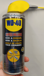
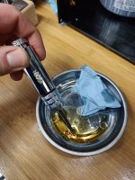
I use the more general Cutting and Drilling fluid from the WD-40 brand (not to be confused with WD40 itself). It comes in a spray can and foams pretty heavy. Most times I use a metal tray, spray some fluid in there and then dip the tapping tools in there. When needed, I wipe off access fluid. That avoids staining the entire workpiece.
Flipping the bracket was the easier move. I looked up the cutting fluid you suggested, hard to get here in the EU.
@srdjant
Sorry, KTM here, only 15W50 fully synthetic
I use the more general Cutting and Drilling fluid from the WD-40 brand (not to be confused with WD40 itself). It comes in a spray can and foams pretty heavy. Most times I use a metal tray, spray some fluid in there and then dip the tapping tools in there. When needed, I wipe off access fluid. That avoids staining the entire workpiece.
Attachments
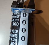
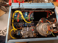
PSU mounting / wiring
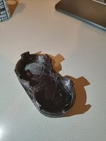
1. Since the capacitors are "floating" and do not properly support the PCB, there is a high protentional for stress on the solder joints. By using "Bison Fast Fix2 - Liquid Plastic" it was possible to build a strong support between the capacitors and PCB. It behaves like a gel, allowing you to easily bridge gaps. Its a 2-component glue, that hardens without shrinking. Perfect for this purpose.
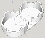
2. Google Sketchup --> sketch a bracket that can be screwed to the chassis bottom and holds the caps in place.
3. 3D printer, picture taken right after printing. You can still see some "stringing". Those can easily be removed by hand, a knife or a little flame does the job too.
4. Installed
5. Wiring the Amplimo toroid to the PSU boards. The black wire terminal is supported with a PCB standoff, to avoid vibrations / stress. All wiring in the Amplimo color style.
1. Since the capacitors are "floating" and do not properly support the PCB, there is a high protentional for stress on the solder joints. By using "Bison Fast Fix2 - Liquid Plastic" it was possible to build a strong support between the capacitors and PCB. It behaves like a gel, allowing you to easily bridge gaps. Its a 2-component glue, that hardens without shrinking. Perfect for this purpose.
2. Google Sketchup --> sketch a bracket that can be screwed to the chassis bottom and holds the caps in place.
3. 3D printer, picture taken right after printing. You can still see some "stringing". Those can easily be removed by hand, a knife or a little flame does the job too.
4. Installed
5. Wiring the Amplimo toroid to the PSU boards. The black wire terminal is supported with a PCB standoff, to avoid vibrations / stress. All wiring in the Amplimo color style.
Attachments
Last edited:
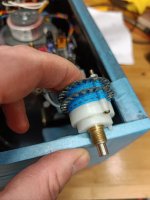
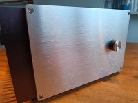
Volume control mounting
The front panel of the "2515" chassis is about 8mm thick, the threads on the Valab stepped attenuator are barely 10mm.... Milling (to create space for the nut) could be an option, but it might limit future options / changes. And I do not have the tools at home to do so. Its not certain the Valab stepped attenuator will stay. So once again, here we go with the 3D printer. If I change to a different volume controller in the future, I can either swap out the adapter for a new one or adapt the front plate to the new attenuator.
High on the wish list would be a Khozmo, they seem to offer a lot of value for the money.
More info here: https://khozmo.com/series_khozmo_attenuator.html
1. Panel too thick / threads not long enough for a secure fit
2. Google Sketchup --> adapter plate (5mm tick, made from PETG). For the ease of printing, both holes are 1-2mm only on the sketch and, after printing, I drilled them to size.
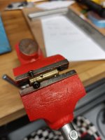
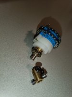
3. Brass shaft coupling, standard size was too long, so drilled + threaded some extra holes. Despite being short, the coupling is very stiff
4. Shortened coupling (attenuator shaft is shortened as well, all to save space)
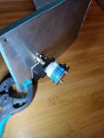
5. Assembled + mounted
6. Front panel + knob covered in tape, all to avoid any damages during the build.
The front panel of the "2515" chassis is about 8mm thick, the threads on the Valab stepped attenuator are barely 10mm.... Milling (to create space for the nut) could be an option, but it might limit future options / changes. And I do not have the tools at home to do so. Its not certain the Valab stepped attenuator will stay. So once again, here we go with the 3D printer. If I change to a different volume controller in the future, I can either swap out the adapter for a new one or adapt the front plate to the new attenuator.
High on the wish list would be a Khozmo, they seem to offer a lot of value for the money.
More info here: https://khozmo.com/series_khozmo_attenuator.html
1. Panel too thick / threads not long enough for a secure fit
2. Google Sketchup --> adapter plate (5mm tick, made from PETG). For the ease of printing, both holes are 1-2mm only on the sketch and, after printing, I drilled them to size.
3. Brass shaft coupling, standard size was too long, so drilled + threaded some extra holes. Despite being short, the coupling is very stiff
4. Shortened coupling (attenuator shaft is shortened as well, all to save space)
5. Assembled + mounted
6. Front panel + knob covered in tape, all to avoid any damages during the build.
Attachments
Neurochrome LM3886DR
What can I say? Probably the easiest / best part of this project. My compliments to @tomchr for his design and provided documentation.
1. Soldered boards, without the LM3886.
Tom, you will probably notice some different capacitors. I'm aware. The caps described in your manual were out of stock (long lead times as well), so I tried to find the best possible replacements. They preferred ones are on back-order, so I might swap them out in the future.
2. Boards mounted to the heatsink --> aligned the LM3886 --> soldered in place on 4 corners --> took all out and soldered all legs properly
3. PCB / solder flux cleaning
4. Mount everything on the heatsink again, ready to be mounted in the chassis
Attachments
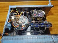
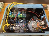
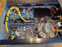
Assembly
1. Heatsink with LM3886DR's mounted
2. Wired, two mistakes found during the first tests:
--> see red circles (caused a little hum)
--> stepped attenuator wired the wrong way around
*note, optic cable was not yet fitted while I made this picture
1. Heatsink with LM3886DR's mounted
2. Wired, two mistakes found during the first tests:
--> see red circles (caused a little hum)
--> stepped attenuator wired the wrong way around
*note, optic cable was not yet fitted while I made this picture
Attachments
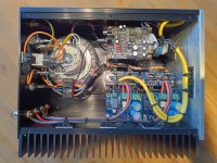
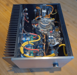
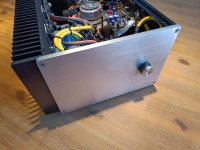
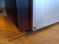
Done . Time to unwrap all the blue (protection) tape!
I'm happy with this amplifier. The build process was fun and the result satisfies me.
. Time to unwrap all the blue (protection) tape! I'm happy with this amplifier. The build process was fun and the result satisfies me.
Attachments
- Home
- Amplifiers
- Chip Amps
- LM3886DR + DAC build