Hello. Does the dc return path resistor influence noise very much ? Is it a design concern ? Does a high value resistance is beneficial in creating a higher input impedance (loosing less signal) or should i use low value to not get too much noise ?
This is the R1 resistor here
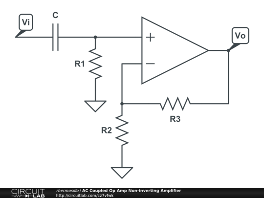
This is the R1 resistor here
The higher R1, the smaller its noise contribution (resistors in series with the source have to be low and those in parallel to the source have to be high for minimum noise) and when a low-impedance source is connected to the input and the DC blocking capacitor is not too small, its noise contribution is quite small anyway.
What source do you intend to connect to the input and what impedance and signal level does it have?
What source do you intend to connect to the input and what impedance and signal level does it have?
Actually, depending on whether you look at the voltage, the current or the available power, large resistors produce more, less or exactly as much thermal noise as small resistors.
As you probably know, you can model a noisy resistor as the series connection of a noiseless resistor and a noise voltage source with an RMS value of sqrt(4 k T B R) over a bandwidth B, where k is Boltzmann's constant, T the absolute temperature and R the resistance. The RMS noise voltage increases with the square root of the resistance.
You can also model it as the parallel connection of an ideal resistor and a noise current source with an RMS value of sqrt(4 k T B/R), the so-called Norton equivalent. The RMS noise current gets smaller with the square root of the resistance.
Your R1 is effectively in parallel with the signal source + coupling capacitor, so its noise current will flow through the signal source and coupling capacitor and cause some voltage drop across their impedances.
Another way to look at it, is to say that the voltage divider consisting of the resistor and the source + coupling capacitor attenuates the noise voltage of the resistor more with a large resistor.
The whole story only holds when there is a signal source connected to the input. With open input, the noise voltage of the resistor gets amplified and a smaller resistor will then lead to less noise - but then again, what's the use of listening to an amplifier with nothing connected to its input?
Last edited:
Depending on the opamp in use, the R1 noise itself might not be the dominant noise source at the output. Also - if C is small there will be an increase in noise at lower frequencies as the effective source impedance rises at LF. Designers normally size C in conjunction with R1 to get a certain LF roll-off (-3dB point) however the LF noise +3dB point depends on the source impedance in conjunction with C.
Depends on your opamp really. For a JFET input opamp, there's no current noise to speak of so the cap's value becomes less crucial. If you choose a very low noise bipolar opamp that'll have significant current noise - the quietest ones have voltage noise roughly equivalent to a 50ohm resistor. To have an effective source impedance below 50ohm at 20Hz would call for a 'lytic but many audiophiles prefer to avoid 'lytics. The source itself isn't likely to be as low noise as 50ohm equivalent anyway.
Why not go for what fits and see if you notice any change when you switch to a more 'reasonable' value?
Why not go for what fits and see if you notice any change when you switch to a more 'reasonable' value?
At first glance a high value of R1 would seem to cause higher noise. After all, the resistor itself will have higher thermal noise (en = 4KTR) and also the input noise current of the opamp will set up a higher noise voltage across R1 (en = in*R).
The saving grace is that at frequencies where the reactance of the input cap is significantly lower than the resistance of R1, R1 will effectively be in parallel with the output impedance of the source driving this circuit. Assuming that the output impedance is significantly lower than R1, R1 will have negligible impact on the noise of the circuit at these frequencies.
Now, note that if you unplug the source, you will get the full impact of R1. So you could have a scenario where you have high output noise when the source is disconnected and low noise when the source is connected. Whether that's acceptable in your application is up to you.
Tom
Depends on your opamp really. For a JFET input opamp, there's no current noise to speak of so the cap's value becomes less crucial.
Indeed, although you still have the sqrt(4 k T B/R1) from resistor R1 as equivalent input noise current. You can make that very small by using a large value for R1. Extreme example: condenser microphones are extremely sensitive to noise current because their small capacitance results in a large impedance, that's why condensor microphones usually have a built-in amplifier with JFET input and 1 Gohm or greater bias resistor.
What kind of source and impedance are we discussing anyway?
Normally for audio signals you'd choose the load resistor to be significantly higher impedance than the source, which means its noise contribution is small compared to the source resistance's noise as its in parallel.Hello. Does the dc return path resistor influence noise very much ? Is it a design concern ? Does a high value resistance is beneficial in creating a higher input impedance (loosing less signal) or should i use low value to not get too much noise ?
The resistances in the feedback network are usually more relevant to noise performance, as they provide a resistive noise source into the inverting input.
But as mentioned the importance of voltage and current noise depends on the impedances, since current noise through an impedance generates voltage noise that combines with other sources of noise. The classic example of this is a MM phono preamp where the source impedance is strongly inductive (which makes it high impedance at higher frequencies, meaning current noise is important)
Thank you.But as mentioned the importance of voltage and current noise depends on the impedances, since current noise through an impedance generates voltage noise that combines with other sources of noise. The classic example of this is a MM phono preamp where the source impedance is strongly inductive (which makes it high impedance at higher frequencies, meaning current noise is important)
By the way does a tube input grid react the same as an opamp ? I means with inductive source like a MM at 20khz we are at several hundeds of kilo ohms, would a tube grid be more noisy (current) than a jfet opamp ?
Thank you.
Thank you.
If i use this ground plane as an electric/magnetic shield, would it mean i am injecting noise in the signal grounded on my shield/groundplane via ?
If i use this ground plane as an electric/magnetic shield, would it mean i am injecting noise in the signal grounded on my shield/groundplane via ?
Thank you. I could not find any value in pA for tube grids, i looked everything on google. Do you know what an ecc83 would produce for example ?As long as the grid is biased negatively with respect to the cathode, and at least 1 V...1.3 V negative, a tube hardly produces any equivalent input noise current. They are somewhat similar to JFETs in that respect.
Last edited:
As long as the tube is in good shape (not gassy or anything), it will be the shot noise of the grid current. Grid current for an ECC83 is guaranteed to be less than 300 nA at VGK < -1.3 V according to the seventh page of this PDF file http://www.r-type.org/pdfs/ecc83.pdf and already less than 300 nA at -0.9 V according to the eighth page (which appears to be a later update).
300 nA corresponds to a shot noise of sqrt(2 q I) ~= 0.31 pA/sqrt(Hz). The grid current and hence its shot noise drops quickly when the grid voltage is made more negative than -0.9 V.
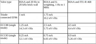
When you want to use tubes for moving magnet amplifiers, it's usually the tube's equivalent input voltage noise you have to worry about. You can reduce the white voltage noise by biasing the tube at a large current and reduce the 1/f voltage noise by biasing it at a low current. Clearly there is an optimum where the total noise is minimal, and that optimum depends on how you weigh different frequencies.
Based on data published by Merlin Blencowe (Merlinb on this forum), I once calculated the attached list. The triode-connected EF86 is based on my own measurements of only two tubes. In the table, you find optimal anode currents and an equivalent white voltage noise level that results in the same total noise as the white + 1/f noise of the tube.
Another thing is record surface noise. If you don't care about the noise level in between records, you really have to mess up big time to end up with an amplifier noise level that's not masked by record surface noise.
300 nA corresponds to a shot noise of sqrt(2 q I) ~= 0.31 pA/sqrt(Hz). The grid current and hence its shot noise drops quickly when the grid voltage is made more negative than -0.9 V.
When you want to use tubes for moving magnet amplifiers, it's usually the tube's equivalent input voltage noise you have to worry about. You can reduce the white voltage noise by biasing the tube at a large current and reduce the 1/f voltage noise by biasing it at a low current. Clearly there is an optimum where the total noise is minimal, and that optimum depends on how you weigh different frequencies.
Based on data published by Merlin Blencowe (Merlinb on this forum), I once calculated the attached list. The triode-connected EF86 is based on my own measurements of only two tubes. In the table, you find optimal anode currents and an equivalent white voltage noise level that results in the same total noise as the white + 1/f noise of the tube.
Another thing is record surface noise. If you don't care about the noise level in between records, you really have to mess up big time to end up with an amplifier noise level that's not masked by record surface noise.
Attachments
Last edited:
Thank you so much MarcelvdG, this is so welcome, i really feel so lonely in life, and i am really triying hard to work well and get something going on in life, its a real struggle for me, i cant make enough money, i feel dumb most of the time when i study electronic..... I am really strulling to keep going in this life and everytime i come to ask help on this forum everyone is so helpful it fuel my heart and allow me to still be on this road... It is off topic but thank you to all of you, its very hard when you are alone, no money but life keeps getting in your way, so thank you very much.
- Home
- Amplifiers
- Chip Amps
- Does the resistor to ground at the input affect opamp noise