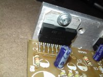
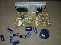
Hi everyone, i hope you all doing well. Anyway I need advice here. Despite worst quality component & circuit design i purchased this kit mainly because the chip is authentic. This kit cost me less than $2, so why not?! Already i have removed most of the components & will heavily modify it. It had BC548 based gain stage or something like that for each channel and cheap 4.7uf electrolytic + 47Kohm carbon film resistor in series with non-inv input! Tda7297 has a fixed gain of 32dB & i believe that's more than enough or maybe way too much for unclipped full output.
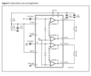
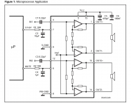
Anyway my question is about mute & st-by operation. The layout has no provision for 'low cost st-by & mute option', instead the manufacturer chose second option (without microprocessor, see attached schematics); 10k resistor + 10uf cap for each pin connected to +VCC. My concern is power on pop noise. Should i increase mute resistor/ capacitor value to increase the delay time to avoid noise ? Btw for power supply i'm going to use 12v bridge type transformer, 18vDC max.
Tda7297 has a fixed gain of 32dB & i believe that's more than enough or maybe way too much for unclipped full output.Anyway my question is about mute & st-by operation. The layout has no provision for 'low cost st-by & mute option', instead the manufacturer chose second option (without microprocessor, see attached schematics); 10k resistor + 10uf cap for each pin connected to +VCC. My concern is power on pop noise. Should i increase mute resistor/ capacitor value to increase the delay time to avoid noise ?
Btw for power supply i'm going to use 12v bridge type transformer, 18vDC max.Attachments
Last edited:
Hi I can recommend using 1 µF film caps for the input caps and a large filter cap. I used 2200 µF 25V Pana FM. Like you say, it does not need a preamp at all. Mine has a 25 kOhm volume control to avoid an "open" power amplifier.
I haven't bothered to change anything with regards to power on plop as it almost hasn't any My board has the resistors and cap against the plop though. The TDA7297 can sound unexpectedly good.
I haven't bothered to change anything with regards to power on plop as it almost hasn't any
My board has the resistors and cap against the plop though. The TDA7297 can sound unexpectedly good.
Last edited:
Sure, i'll change input capacitors and big supply cap. But my question is about st-by and mute. Which option should i select for 18v operation? The layout has no room for 'stand alone low cost st-by mute' voltage divider option instead it has 10kohm resistor +10uf cap for each pin tied to +V, although this is recommend for microprocessor based operation(see my earlier post for datasheet recommendations).
Last edited:
Yes I understood perfectly. Maybe ... just maybe that works fine too. You assume it will plop but maybe it doesn't.
If your assumption turns out to be truth then remove one of the resistors and a cap let's say R2/C4. Then tie pin 6 and 7 together with a piece of solid thin wire, use a 47 kOhm in parallel to C2, replace R1 for a 47 kOhm and it is solved. It is simple to solve really.
If your assumption turns out to be truth then remove one of the resistors and a cap let's say R2/C4. Then tie pin 6 and 7 together with a piece of solid thin wire, use a 47 kOhm in parallel to C2, replace R1 for a 47 kOhm and it is solved. It is simple to solve really.
Last edited: