Dear all please suggest what can i do... Basically its a tda2030 based 2.1 circuit for some reason the satellite speakers makes a humming noise. It goes away as soon as i touch the heatsink with hand. So i thought it might be grounding issue as the heatsink was negative thus made a hole in the heatsink and took a wire and connected it to ground (used isolator to separate ic from heatsink) but now the noise is same as before and cant touch the heatsink as it shows high voltage that is dangerous to touch with bare hand. Please help 🙏

This sound a little bit dangerous (I am understating this to avoid writing in REALLY BIG LETTERS).
Are you saying that by grounding the heatsink you measure a dangerously high voltage on the heatsink?Because if this is too high to be safe - so will the voltage on the ground be.
I advise EXTREME CAUTION with anything you do from now on with this amplifier - no electrocution, please!!
How are you measuring the voltage on the heatsink?
Cheers,
Martin
Thank you for your concerns Martin. Its not to the point that might burn but i tested with digital meter that shows its not safe to touch with hand. If i connect it back to negative everything is normal like before (with noise that goes away if i touch the heatsink) the noise is high frequency and only satellite speakers makes that noise. Honestly i am at a loss with this amp. Anything you would recommended that i can try for that noise?
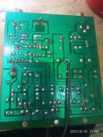
I have attached the circuit picture if that helps you to understand better
Thank you
Neon
I have attached the circuit picture if that helps you to understand better
Thank you
Neon
Attachments
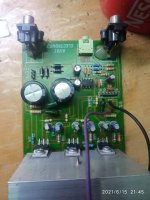
It seems your capacitors are dying, one is swollen to the point of explosion.
If you get the lightning symbol on your meter, it activates above 24V for many meters.
Grounding the heatsink is a sensible idea and should be done anyway.
Beyond replacing the power supply capacitors, I would also replace the 560 ohm resistors with about 1.2k. This will bring down the gain, make the amp more linear and reduce the effect of stray noise.
Just because you hear the noise in the smaller speaker doesn't mean the sub doesn't have it, it's just probably too high in frequency.
Thank you for your concerns Martin. Its not to the point that might burn but i tested with digital meter that shows its not safe to touch with hand. If i connect it back to negative everything is normal like before (with noise that goes away if i touch the heatsink) the noise is high frequency and only satellite speakers makes that noise. Honestly i am at a loss with this amp. Anything you would recommended that i can try for that noise?
I have attached the circuit picture if that helps you to understand better
Thank you
Neon
Where are you measuring the voltage? - one probe on the heatsink, but where do you connect the other probe?
Cheers,
Martin
It seems your capacitors are dying, one is swollen to the point of explosion.
If you get the lightning symbol on your meter, it activates above 24V for many meters.
Grounding the heatsink is a sensible idea and should be done anyway.
Beyond replacing the power supply capacitors, I would also replace the 560 ohm resistors with about 1.2k. This will bring down the gain, make the amp more linear and reduce the effect of stray noise.
Just because you hear the noise in the smaller speaker doesn't mean the sub doesn't have it, it's just probably too high in frequency.
Hello, Sangram thank you for you time. I checked the cap with tester but there was low Internal resistance so didn’t changed them but if you recommend doing then will change it along with resistor as you said. The noise is high frequency prolly thats why not hearing it from sub. I will let you know as soon as i change those parts.
Where are you measuring the voltage? - one probe on the heatsink, but where do you connect the other probe?
Cheers,
Martin
New to this forum so couldn’t reply properly but yes as i said one time in PE another time with transformer 0v
On my 2.1 kit the supply is off a 12-0-12 transformer, it measures 19.2 at the amp supply input to amp ground.
Check the transformer after removing from circuit, it may read 18 volts AC, one side to center tap, that is normal.
The 2 wires that go to the bridge are the outer 12V wires from transformer, center wire goes to ground.
If you see 36 volts, something is wrong.
Also, these chips will not live long at that voltage. I assume they are Chinese 2030...
Remove from heat sink and fit them back after coating with a film of heat sink compound.
Change the main caps to Keltron, at least 50 or better 63V rating, and put a small pf across the main capacitors, helps reduce noise.
Last edited:
Hi
No problem - that is why I rephrased my question.
What do you mean by "PE"? - I am afraid that I still dont understand what voltage you have measured.
But let me try this from a different angle:
It is a little bit unprecise to assess the circuit by the two pictures of the assembled board - but if I get it right, the AC input (12Vac - 0 - 12Vac) from the transformer is connected such that the 0 - the middle pin in the 3-pin connector - from the transformer is connected to amplifier ground.
This is where you have soldered the black wire.
When measuring the voltage on the heatsink, then measure the voltage between the 0 on the transformer (also called the center tap) and the heatsink - with and without the short between ground and the heatsink.
Use the DC-setting on your multimeter and tell us what voltage you measure.
The second of above measurements should give you 0V - otherwise you are not measuring where I explain.
Then measure - using the AC-setting on your multimeter - the voltage from 0 to the two 12VAC connections and tell us what you measure.
All of above is only to understand why you seem to have measured more than 36V anywhere in this amplifier - because as NareshBrd explains thisshould not happen for that chip amplifier.
Next - using the ohm-range on the multimeter: WITHOUT POWER connected measure the resistance from the small cooling fin on each amplifier chip to the heatsink.
There seems to be proper isolation in between - but this step is to ensure that the isolation actually works.
Third: Look at the solder joint on pin 3 on the middle TDA2030 - from the picture it looks faulty.
Fourth: If you have access to an oscilloscope - then tell us. That will make the next steps easier.
Cheers,
Martin
19.2 Volts DC, at supply to IC
Off load, the transformer volts go higher than rated.
But 36 is way too high....or the reading is from the outer two wires of the transformer secondary, at no load. But in circuit that should not happen.
Check the bridge diodes, with a tester, should be at least 3 amp types, if not, put bigger ones.
And see they are put correctly, that happens too in cheap kits.
And see if the transformer hums...
But first replace the capacitors, they look about to explode.
And they are a possible reason for this problem.
In an emergency, the big capacitors from a computer SMPS can be used for checking, if nothing else is handy, those are 330uf/200 V, sometimes 220 or 470 uF are seen, or take a 1500 or 2200 from low volts side if at least 25V
Last edited:
I will try to describe the situation again just quick, this is the cheapest 2.1 we could find, we connected the transformer 12-0-12 to the circuits ac in 12-0-12 with no rectifier or filter canps, just the ones that are already there, and the two satellite speakers had high frequency jitter which would disappear upon touching the heatsink even from a bed ac isolated, since it sounded like something wasn't grounded we checked the dc voltage between the heatsink and the 0v and there was negative 12v, usually heatsinks are grounded so we put plastic washers and mica to isolate the heatsink from each of the chips, then tested to find the the jitter persisted (note the middle legs are already shorted in the PCB), and grounded the heatsink to the transformer 0v still jitter , this time upon touching the heatsink I received a shock and then measured above 36vac between the heatsink and the protective earth terminal of the mains, but no voltage between the heatsink and the 0v of the transformer, and still the jitter persists
the tda chip backside, the metal is connected to -volt of the board. This must be a dual supply, isnt it? Suggest you to check if the heat sink is thoroughly isolated from the thermal tab. even after we place mica washers, i have noticed the screw that we use making contact with the heat sink. just check that once. if that happens, noise will come.
you should not measure negati)ve volt on heatsink with respect to ground on heatsink. i am sure that the chip metal tab is in contact with the heatsink. Do a continuity test between tda chip metal tab( not the mica kit screw) and heat sink. there should be no beep .Happens quite common in chipamps
Fine. Are you testing this with source connected?Or without source? Sometimes,i have seen DVD and CD players give high current in ground. That noise may be a ground loop problem. That high voltage may also be through the smps of dvd or source,just in case. Do you get noise and hum even without source being connected?
- Home
- Amplifiers
- Chip Amps
- Tda2030 2.1 amp noise problem