Hi everyone,
I was wondering if I could get some help with an issue I'm having with a chipamp build.
I built it using the TDA2050 snubberized power supply:
It hums, a lot. It has a very loud 100hz hum (I'm in the UK).
I have played around with a cheap digital scope I have, and it seems like the issue is with the +ve supply, which has 1.5v of a sawtooth 100hz signal in it. It's also slightly lower in voltage output (~20v compared to -25v -ve, which is what I expected).

This signal is exactly mirrored on the output too.
On the -ve, there is the same signal, but only around 25-30mv:

Interestingly (maybe), the mirrored signal on the output disappears if I touch the audio input. If I touch the audio in on the right channel, the right sawtooth output signal disappears at the right speaker terminal, but it remains on the left. If I touch the left in, it disappears on the left out but not the right.
I've tried moving the wires around, changing ground positions, moving the transformer, no change. The rectifier tests OK.
The only thing I haven't done is change the 10,000uf cap on the +ve rail, which I'm going to do today. It was a brand new Nichicon cap, does it seem possible that this is the problem and it's just not getting smoothed?
It seems like something else might be going on.

I was wondering if I could get some help with an issue I'm having with a chipamp build.
I built it using the TDA2050 snubberized power supply:
It hums, a lot. It has a very loud 100hz hum (I'm in the UK).
I have played around with a cheap digital scope I have, and it seems like the issue is with the +ve supply, which has 1.5v of a sawtooth 100hz signal in it. It's also slightly lower in voltage output (~20v compared to -25v -ve, which is what I expected).
This signal is exactly mirrored on the output too.
On the -ve, there is the same signal, but only around 25-30mv:
Interestingly (maybe), the mirrored signal on the output disappears if I touch the audio input. If I touch the audio in on the right channel, the right sawtooth output signal disappears at the right speaker terminal, but it remains on the left. If I touch the left in, it disappears on the left out but not the right.
I've tried moving the wires around, changing ground positions, moving the transformer, no change. The rectifier tests OK.
The only thing I haven't done is change the 10,000uf cap on the +ve rail, which I'm going to do today. It was a brand new Nichicon cap, does it seem possible that this is the problem and it's just not getting smoothed?
It seems like something else might be going on.
It won't be the caps or their values. An amp like this should be silent even with 1000uF let alone 10,000uF reservoir caps.
The unbalanced rails are a puzzle but nothing to do with the hum in the sense of them being different.
Check the two secondaries really are separate i.e. it really is a four wire connection and not three with a shared centre tap.
Check the AC voltage (use a DVM) across each winding. They should both be the same.
It is possible that the amp has a DC offset and that it is drawing current from predominantly one rail which would pull the voltage down a little on that side... worth checking.
If you take a spur from the centre point of the two reservoir caps and use the end of that spur alone as a clean ground then the amp should not hum. Couple up just one channel to begin with and make sure that is silent. You can return the speaker negative point to the reservoir caps but nothing else. All sensitive ground points are to be referred to the clean ground.
Follow what was done here, its a long thread but all the answers should be here:
Complete novice alert! *don't read if easily annoyed by stupid questions*
The unbalanced rails are a puzzle but nothing to do with the hum in the sense of them being different.
Check the two secondaries really are separate i.e. it really is a four wire connection and not three with a shared centre tap.
Check the AC voltage (use a DVM) across each winding. They should both be the same.
It is possible that the amp has a DC offset and that it is drawing current from predominantly one rail which would pull the voltage down a little on that side... worth checking.
If you take a spur from the centre point of the two reservoir caps and use the end of that spur alone as a clean ground then the amp should not hum. Couple up just one channel to begin with and make sure that is silent. You can return the speaker negative point to the reservoir caps but nothing else. All sensitive ground points are to be referred to the clean ground.
Follow what was done here, its a long thread but all the answers should be here:
IT WORKS! It only bloody works doesn't it?!!!!!!! Thank you SO much, I was really losing the will to carry onI am one happy soul
Complete novice alert! *don't read if easily annoyed by stupid questions*
Thank you for your response.
Just to confirm, you don't think it could be a 'bad' filter cap on the +ve, rather than a value issue?
I'm getting 20vac across the -ve AC secondary, and a little less across the +ve, around 18vac. I don't think this would make a difference, but I have the 0-18v output for each of the secondaries wired the opposite way round on each of the rectifiers.
If I use a lightbulb limiter to turn it on, the light comes on and stays on relatively bright, rather than dimming back down.
I am getting DC across the output with speakers connected (18v). How would I check for a DC offset?
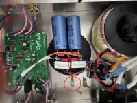
Everything grounded to one point, which is connected directly to a spur from the centre point of the two caps. It wasn't on the pic, but I have since move the board ground to the filter capacitor ground point, which is the only one now except for the mains safety ground.
As it's the stereo LM4766 and I'm using a PCB board, I'm not sure how to go about just doing one channel at a time in the way it was done on that thread. I was also hoping I could work with what I have here as much as possible and try to avoid buying anything new for the time being, if possible. I will give a proper read over and try and think about how to relate it to my issues.
I've checked over the board connections, everything seems fine. Solder joints look good, I can't see any shorts between contacts. I've checked the layout of the components on the board repeatedly and I'm certain nothing's in the wrong place etc.
Just to confirm, you don't think it could be a 'bad' filter cap on the +ve, rather than a value issue?
I'm getting 20vac across the -ve AC secondary, and a little less across the +ve, around 18vac. I don't think this would make a difference, but I have the 0-18v output for each of the secondaries wired the opposite way round on each of the rectifiers.
If I use a lightbulb limiter to turn it on, the light comes on and stays on relatively bright, rather than dimming back down.
I am getting DC across the output with speakers connected (18v). How would I check for a DC offset?
Everything grounded to one point, which is connected directly to a spur from the centre point of the two caps. It wasn't on the pic, but I have since move the board ground to the filter capacitor ground point, which is the only one now except for the mains safety ground.
As it's the stereo LM4766 and I'm using a PCB board, I'm not sure how to go about just doing one channel at a time in the way it was done on that thread. I was also hoping I could work with what I have here as much as possible and try to avoid buying anything new for the time being, if possible. I will give a proper read over and try and think about how to relate it to my issues.
I've checked over the board connections, everything seems fine. Solder joints look good, I can't see any shorts between contacts. I've checked the layout of the components on the board repeatedly and I'm certain nothing's in the wrong place etc.
The offset is the main problem. It should be close to zero. 18 volts will allow over 2 amps to flow in the speaker and that in turn would pull the supply voltage down on one rail and cause the large ripple you see.
You need to work on this with no speaker connected and with the inputs shorted.
It might help if you post a diagram of the exact circuit you have used for the amp and showing all component values.
You need to work on this with no speaker connected and with the inputs shorted.
It might help if you post a diagram of the exact circuit you have used for the amp and showing all component values.
You could also post the voltages you measure (no speaker attached) that are present on all the pins of the chip. It is essentially just a 'power opamp' and will obey all the normal rules.
It may be oscillating... a scope would prove that instantly. You mentioning that touching the inputs alters things points to that theory.
We need to see the exact circuit you have used.
It may be oscillating... a scope would prove that instantly. You mentioning that touching the inputs alters things points to that theory.
We need to see the exact circuit you have used.
OK, I will short the inputs and disconnect the speakers.
Do you want the voltages on the pins after or before I've done this? Or both?
Here is the schematic of the build. It's using a KMTech board from eBay.

The +ve and -ve capacitors are shared between channels, as is the 100uf. The 22uf caps are electrolytic.
Do you want the voltages on the pins after or before I've done this? Or both?
Here is the schematic of the build. It's using a KMTech board from eBay.
The +ve and -ve capacitors are shared between channels, as is the 100uf. The 22uf caps are electrolytic.
With speakers disconnected and inputs shorted (I assumed to ground rather than each other, but I can do it again if not).
1: -0.13mv
2: 27.7v
3: -0.5mv
4: -27.7v
5: -0.02mv
6: -178.7mv
7: -6.7mv
8: -0.01mv
9: varied, 60-100mv
10: 0.3mv
11: -178.7mv
12: -2.7mv
13: -0.1mv
14: varied, 60-100mv
15: 27.6v
The output scope trace I posted above just had the 1.5v(ish) 100hz sawtooth waveform on it, though it's possible there was some other thing high frequency going on which that was hiding.
Inputs shorted to ground is perfect...
Now those voltages look pretty good at face value... and there doesn't seem to be any 18 volt DC offset here because pins 1 and 3 (the output) are at near zero. So something has changed.
With everything just as it is now just double check that there is indeed no DC on the speaker terminals of the amp.
One thing puzzles me (and I've never used or researched the LM4766) is that the input on pins 8 and 13 are shown 'floating' and without any ground referencing resistor. Normally with any opamp or audio output chip there would be a resistor to ground.
If the speaker terminals do indeed have no DC in this condition then switch off and couple up the speakers again and retest. Leave the inputs shorted of course. And always use the bulb tester.
If that is OK then I think we have to add a resistor of 20k or 22k from the input to ground. Now with the short removed retest again.
Also I see there is no Zobel network present but we can look at that later.
lets hope so.The circuit looks to be lifted from the data sheet and that shows no resistor... and this really confirms the message that data sheet examples are often not fully worked examples that can be built and used as you might think. It also shows no output inductor or Zobel.
It should all work once these things are attended to.
Thanks for your help so far!
Ok, I double-checked and there’s no dc on the terminals.
There’s now zero hum coming through the speakers.
I actually have two 20k resistors to hand. Can these go straight on the input rca sockets or are they better on the chip?
I wondered about the resistor to ground. I’ve only ever built valve guitar amps so hifi is all new to me, just assumed it was different.. I actually only decided to build a gainclone after turning an old amp into a valve preamp/buffer. I went with the LM4766 just out of cheapness!
I actually already swapped it to one ground rather than two - I copied the grounding scheme from the valve guitar amp world which uses one for preamp next to input, one for power amp next to caps.
As soon as I started reading around for troubleshooting I realised that was a mistake!
As soon as I started reading around for troubleshooting I realised that was a mistake!
I actually have two 20k resistors to hand. Can these go straight on the input rca sockets or are they better on the chip?
Put the upper end of the 20k input reference resistors as close as possible to the chip pins...the same rule applies even more to the -input pin (feedback and gain setting resistors).
I wondered about the resistor to ground. I’ve only ever built valve guitar amps so hifi is all new to me, just assumed it was different.. I actually only decided to build a gainclone after turning an old amp into a valve preamp/buffer. I went with the LM4766 just out of cheapness!
Don't worry, the LM4766 is a very close cousin of the LM3886, almost like they put 2 x LM3886s in one case and halved the number of output transistors as well as halved the slew rate as well (for the latter I'm not sure that's true). In any case, the LM4766/LM3886 is SOTA to this day.
OK. So, I soldered the 20k resistors between pins 8 (in) and 5 (gnd), and pins 13 (in) and 10 (gnd) on the underside of the board.
Powered up, amp was totally silent, tested for DC, no issues. Checked the voltages on all the pins again, everything was still good.
I don't have an RCA cable, so I had to crocodile clip on to a guitar lead coming out of my computer. I have the parts to make the cable, but wanted to get it working first.
Totally silent. Then realised I hadn't put a jumper across the mute button.
It now works!
It's totally silent except for when I clip on to the hot of the lead. If I hold the earth and the hot crocodile clip cables tight next to each other, it quietens down considerably, which makes me think the issue is the cables... not anything in the amp?
I feel like if there was a ground loop issue to do with the power supply I would hear it whether connected to an input source or not... right? I think?
The only other issue is the channels sound slightly different. The speakers I'm using are just some junk ones I picked up in a charity shop though, so I'm trying to work out if it's the amp or if the speakers sound slightly different to each other.
OK. So, I soldered the 20k resistors between pins 8 (in) and 5 (gnd), and pins 13 (in) and 10 (gnd) on the underside of the board.
While for a newbie any ground on the circuit or on the pcb is a good place to solder something on it, the truth is very far from that. Therefore, if you want to do something properly and learn something along the way, you have to read well and put it into practice exactly as the more experienced tell you. If Mooly and I tell you to solder the lower end of the ground reference resistor at the input of the amplifier to the signal ground, then please do exactly as said because there will be less problems later.
I don't have an RCA cable, so I had to crocodile clip on to a guitar lead coming out of my computer. I have the parts to make the cable, but wanted to get it working first.
I understand your desire to have an amplifier that works "properly" as soon as possible, but there is no room for shortcuts here...make/buy a cheap but technically correct interconnection cable.
I feel like if there was a ground loop issue to do with the power supply I would hear it whether connected to an input source or not... right? I think?
I expect the amp to be totally silent in only two cases for now: a) when nothing at the input is connected and b) when only one channel (left or right) is connected at the amplifier input. The moment you connect both channels (left and right) at the amplifier input, the same moment a ground loop will appear inside the amplifier that no longer will be silent...but we will solve this later with the already mentioned 10R resistors.
The only other issue is the channels sound slightly different. The speakers I'm using are just some junk ones I picked up in a charity shop though, so I'm trying to work out if it's the amp or if the speakers sound slightly different to each other.
Replace the left with the right speaker and listen again.
- Home
- Amplifiers
- Chip Amps
- LM4766 Hum Issue (first chipamp build)